
Last updated: 11-05-2014 01:16
| << Back | HOME | Next >> |
The UNIX and GNU/Linux operating system has always proven its versatility in aspects related to communication and information exchange. Wide Area Networks (WAN) networks based on serial modems, Frame Relay, Plesiochronous Digital Hierarchy (PDH) E1 and T1 circuits in 2.048 and 1.544 Megabit/second (Mb/s) blocks and 155 Mb/s Synchronous Optical Networking (SONET) and Synchronous Digital Hierarchy (SDH) have been replaced by Gigabit/second (Gb/s) speed fibre and copper Metro Ethernet Metropolitan Area Networks (MAN) technologies. Home users are receiving broadband with a mix of Passive Optical Network (PON) technologies, various flavours of Digital Subscriber Line (DSL), Data Over Cable Service Interface Specification (DOCSIS) wireless technologies from Institute of Electrical and Electronics Engineers (IEEE) 802.16 WiMAX, Long Term Evolution (LTE) and IEEE 802.11 based Wireless technologies offering speeds from 3 Megabit/second (Mb/s) to 200 Mb/s. Home users and companies have Local Area Networks (LAN) within their premises to interconnect their computing devices.
|
All of these technologies offer a Data Link framing at layer 2 of the Open Standards Interconnect (OSI) 7 layer communications model from the International Standards Organisation (ISO). The handling of the upper layers is mapped to the Department of Defence (DoD) 4 Layer Model, particularly layer 3, Internet layer (OSI Network layer) and layer 4, Host to Host layer (OSI Transport layer) is carried out by the Internet protocol suite (IPS) commonly called the Transmission Control Protocol/Internet Protocol (TCP/IP) protocol suite. While TCP/IP is mapped to the DOD 4 layer model it is common that layers 3 and 4 are referred to by their OSI names, Network and Transport layers.
TCP/IP is a set of basic protocols that meet the different needs in computer-to-computer communication, such as Transmission Control Protocol (TCP), User Datagram Protocol (UDP), Internet Protocol (IP), Internet Control Message Protocol (ICMP), Address Resolution Protocol (ARP), Dynamic Host Configuration Protocol (DHCP), Domain Name Service (DNS) and in Internet Protocol version 6 (IPv6), ICMPv6, DHCPv6, ....
TCP/IP is most frequently used by most current users to remotely connect to other computers Secure Shell (SSH), to use remote files with Network File System (NFS) or to transfer them with File Transfer Protocol (FTP) or Secure FTP (SFTP) or access webpages with HyperText Transfer Protocol (HTTP) the web standard markup protocol.
Example login to a remote server ftacademy.org by user dobriain.
  $ ssh dobriain@ftacademy.org

  dobriain@ftacademy.org's password:
  Linux fta.obriain.com 3.2.0-4-amd64 #1 SMP Debian 3.2.54-2 x86_64

  The programs included with the Debian GNU/Linux system are free software;
  the exact distribution terms for each program are described in the
  individual files in /usr/share/doc/*/copyright.

  Debian GNU/Linux comes with ABSOLUTELY NO WARRANTY, to the extent
  permitted by applicable law.
  Last login: Wed Mar 26 16:21:21 2014
  dobriain@ftacademy:~$
The most important traditional TCP/IP services are:
The progress in the technology and the increasingly lower cost of computers has meant that determined services have specialised and are now configured on determined computers working in a client-server model. A server is a system that performs specific services for the rest of the network or connected clients. A client is another computer that uses this service. All of these services are generally offered within TCP/IP:
TCP/IP is in fact two communication protocols between hosts (computers) that are independent to each other. IP defines the protocol at the Internet/Network layer to identify the networks and establish the pathways between different computers. TCP defines the communication rules so that a host computer can talk to another computer (Host to Host/Transport layer). TCP is a connection-oriented protocol and the communication is considered as a data stream. The receiving host verifies receipt of data in blocks to the sending host before it sends another block, in this way the data sent over the link is verified as received.
Another Host to Host/Transport layer protocol is the UDP, which treats the data as a message (datagram) and sends packets. It is considered a connectionless protocol as the sending host receives no confirmation of receipt of the data that is sent (much like a standard letter in the mail system). The advantage of this is less overload on the network than a TCP connection, but it is obviously less reliable (the packets may not arrive or arrive duplicated). It is commonly used with protocols that are sensitive to packet delay like Voice over IP (VoIP) and video streaming.
To summarise, TCP/IP is a set of protocols including IP, TCP, UDP that provide a set of low-level functions used by most of the applications. Some of the protocols that use the above mentioned services were designed by Berkeley, Sun or other organisations. They are not included (officially) as part of the Internet Protocol Suite (IPS). However, they are implemented using TCP/IP and they are therefore considered as a formal part of IPS. A description of the protocols available by Internet can be found in the Internet Engineering Task Force (IETF) Request For Comment (RFC) 1011. There is currently a new version of protocol IPv6, also called IP Next Generation (IPng) which replaces IP version 4 (IPv4). It is defined in RFC2460 and is updated in a series of additional RFCs. This protocol significantly improves the previous ones in elements such as having a greater number of nodes, traffic control, security or improvements in the routing.
From the physical point of view (layer 1 of the OSI model), the most commonly used hardware for LAN is that known as Ethernet (FastEthernet (FE) or GigaEthernet (GbE)). Its advantages consist of a lower cost, acceptable speeds (100 Mb/s, 1 Gb/s or 10 Gb/s) and its user-friendly installation.
 |
Presentation is either via copper twisted pair, fibre or wireless.
100Base-TX (uses 2 bi-directional pairs in Category 5e (CAT5e) or above), 1000Base-T (uses 4 bi-directional pairs in CAT-5e or above) and 1000Base-TX (uses 2 bi-directional pairs in CAT-6, CAT-7 only). The standard copper pinout is given in the diagram above. All of these copper technologies are limited to a distance of 100 metres.
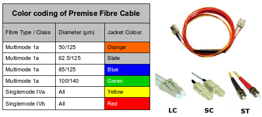 |
Alternatively Ethernet can be delivered via optical fibre. An optical fibre is a small narrow tube plastic or glass which guides light along its length by total internal reflection. The particular wavelengths used, 850, 1300 and 1550 nano metres (nm), correspond to wavelengths where optical light sources, lasers or Light Emitting Diodes (LED) are easily manufactured. There are main types of fibre;
The other type of Ethernet LAN is Wireless. These are IEEE 802.11 based Wireless Fidelity (WiFi) family of specifications for wireless LAN (WLAN) technology. Wireless LANs are organised with Access Points (AP) radio transmitters that allow hosts (computers, mobile devices, ...) to connect to a specific Service Set IDentifier (SSID) which defines the wireless network. Security is an essential element of wireless networks and Wi-Fi Protected Access version 2 (WPA2) (also called Robust Security Network (RSN)) is an implementation of the IEEE 802.i standard used today. Older security protocols like Wireless Encryption Protocol (WEP) and Wi-Fi Protected Access(WPA) are considered less secure.
| Standard | Description | |
|---|---|---|
| 802.11 | Applies to wireless LANs and provides 1 or 2 Mbps transmission in the 2.4 GHz band using either Frequency Hopping Spread Spectrum (FHSS) or Direct Sequence Spread Spectrum (DSSS). | |
| 802.11a | An extension to 802.11 that applies to wireless LANs and provides typically 25 Mbps to a maximum of 54 Mbps in the 5GHz band. 802.11a uses an Orthogonal Frequency-Division Multiplexing (OFDM) encoding scheme rather than FHSS or DSSS. Max range is 30 M. | |
| 802.11b | An extension to 802.11 that applies to wireless LANS and provides 11 Mbps transmission (with a fallback to 5.5, 2 and 1 Mbps) in the 2.4 GHz band. 802.11b uses only DSSS. 802.11b was a 1999 ratification to the original 802.11 standard, allowing wireless functionality comparable to Ethernet. Max range is 30 M. | |
| 802.11g | Applies to wireless LANs and provides typically 24 Mbps to a maximum of 54 Mbps in the 2.4 GHz band. It also uses OFDM. Max range is 30 M. | |
| 802.11n | New standard to give typically 200 Mbps to a maximum of 540 Mbps out to 50 M in either the 2.4 or 5 GHz bands. It uses Multiple In, Multiple Out (MiMo) antennas. | |
Determine the wireless interface from the kernel ring buffer. Also use the iw dev to get a listing of all wireless hardware devices on the system.
   $ dmesg |grep Wireless
  [   20.615523] eth1: Broadcom BCM4359 802.11 Hybrid Wireless Controller 6.30.223.141 (r415941)


  $ iw dev
  phy#0
  	Interface eth1
  		ifindex 3
  		type managed
Now using the wireless iw utility with the interface eth1 just discovered get information on the wireless interface.
  $ iw dev eth1 info
  Interface eth1
  	ifindex 3
  	type managed
  	wiphy 0
In GNU/Linux, Ethernet is called with ethx (where, "x" indicates an order number beginning with 0), the interface to serial lines (modems) is called up with pppx, Point to Point Protocol (PPP). These names are used by the commands to configure them and assign them the identification that will subsequently permit them to communicate with other devices in the network. This may mean that we have to include the appropriate modules for the appropriate device Network Interface Card (NIC) in the kernel or as modules, and this means compiling the kernel after choosing, the appropriate NIC, with, for example, make menuconfig, indicating it as internal or as a module (in the latter case, the appropriate module must also be compiled). In reality it is typical for the GNU/Linux installation to incorporate the appropriate generic module for the hardware.
Listing the available interfaces:
  $ ifconfig -a

  eth0      Link encap:Ethernet  HWaddr 28:d2:44:19:83:95
            UP BROADCAST MULTICAST  MTU:1500  Metric:1
            RX packets:0 errors:0 dropped:0 overruns:0 frame:0
            TX packets:0 errors:0 dropped:0 overruns:0 carrier:0
            collisions:0 txqueuelen:1000
            RX bytes:0 (0.0 B)  TX bytes:0 (0.0 B)

  eth1      Link encap:Ethernet  HWaddr 1c:3e:84:ed:99:0b
            inet addr:192.168.43.222  Bcast:192.168.43.255  Mask:255.255.255.0
            inet6 addr: fe80::1e3e:84ff:feed:990b/64 Scope:Link
            UP BROADCAST RUNNING MULTICAST  MTU:1500  Metric:1
            RX packets:1068090 errors:0 dropped:0 overruns:0 frame:1016162
            TX packets:908026 errors:0 dropped:0 overruns:0 carrier:0
            collisions:0 txqueuelen:1000
            RX bytes:1014889719 (1.0 GB)  TX bytes:135467503 (135.4 MB)
            Interrupt:17

  lo        Link encap:Local Loopback
            inet addr:127.0.0.1  Mask:255.0.0.0
            inet6 addr: ::1/128 Scope:Host
            UP LOOPBACK RUNNING  MTU:65536  Metric:1
            RX packets:92579 errors:0 dropped:0 overruns:0 frame:0
            TX packets:92579 errors:0 dropped:0 overruns:0 carrier:0
            collisions:0 txqueuelen:0
            RX bytes:8690656 (8.6 MB)  TX bytes:8690656 (8.6 MB)
This command shows all of the default interfaces/parameters for each one, it is a depreciated command however and the new ip link show gives the same output but in a much less neat manner.
  $ ip link show

  1: lo: <LOOPBACK,UP,LOWER_UP> mtu 65536 qdisc noqueue state UNKNOWN mode DEFAULT
      link/loopback 00:00:00:00:00:00 brd 00:00:00:00:00:00
  2: eth0: <NO-CARRIER,BROADCAST,MULTICAST,UP> mtu 1500 qdisc pfifo_fast state DOWN mode DEFAULT qlen 1000
      link/ether 28:d2:44:19:83:95 brd ff:ff:ff:ff:ff:ff
  3: eth1: <BROADCAST,MULTICAST,UP,LOWER_UP> mtu 1500 qdisc pfifo_fast state UP mode DORMANT qlen 1000
      link/ether 1c:3e:84:ed:99:0b brd ff:ff:ff:ff:ff:ff
The network devices can be seen in the /dev directory, where there is a a special file, (which may be a block file or a character file, according to the transfer) that represents each hardware device.
Communication involves a series of concepts:
00:88:40:73:AB:FF (octal) 0000 0000 1000 1000 0100 0000 0111 0011 1010 1011 1111 1111 (binary)) or an EUI-64, a 64-bit number (i.e. 00:88:40:FF:FE:73:AB:FF (octal) 0000 0000 1000 1000 0100 0000 1111 1110 0111 0011 1010 1011 1111 1111 (binary)). The EUI is burnt on the physical hardware of the the Ethernet driver (NIC) and that is recorded by the manufacturer as it must be is globally unique. (this number must be the only one globally, each NIC manufacturer has a pre-allocated range).
  $ cat /etc/hostname

  myHostname
  $ cat /etc/hosts

  127.0.0.1	localhost
  127.0.1.1	myHostname

  # The following lines are desirable for IPv6 capable hosts
  ::1     ip6-localhost ip6-loopback
  fe00::0 ip6-localnet
  ff00::0 ip6-mcastprefix
  ff02::1 ip6-allnodes
  ff02::2 ip6-allrouters
named).
named).
  $ less /etc/services

  tcpmux		1/tcp				# TCP port service multiplexer
  echo		7/tcp
  echo		7/udp
  discard		9/tcp		sink null
  discard		9/udp		sink null
  systat		11/tcp		users
  daytime		13/tcp
  daytime		13/udp

  ~~~~  		~~~/~~~         ~~~

  vboxd		20012/udp
  binkp		24554/tcp			# binkp fidonet protocol
  asp		27374/tcp			# Address Search Protocol
  asp		27374/udp
  csync2		30865/tcp			# cluster synchronization tool
  dircproxy	57000/tcp			# Detachable IRC Proxy
  tfido		60177/tcp			# fidonet EMSI over telnet
  fido		60179/tcp			# fidonet EMSI over TCP
  ...
  $ ip -4 route list

  default via 192.168.22.1 dev eth1  proto static
  192.168.22.0/24 dev eth1  proto kernel  scope link  src 192.168.22.159  metric 9
Visualisation of the routing's configuration.
  $ cat /etc/resolv.conf

  nameserver 8.8.8.8
  $ ip -4 neigh list

  192.168.43.1 dev eth1 lladdr 5c:f8:a1:b3:79:c2 REACHABLE
  $ ip -6 neigh list

  2501:f2b30:2a0a::1 lladdr 5c:f8:a1:b3:79:c2 router REACHABLE
The way for a programmer to use them is through an Application Programming Interface (API) which implements this source-code interface. For TCP/IP, the most common API is the Berkeley Socket Library (Windows uses an equivalent library that is called Winsocks). This library makes it possible to create a communication end-point (socket), associate it to a remote node and port (bind) and offer the communication service (through connect, listen, accept, send, sendto, recv, recvfrom, for example). The library also provides a more general communication mode (AF INET family) and more optimised communications for cases in which the process are communicating within the same machine (AF UNIX family). In GNU/Linux, the socket library is part of the C standard library, Libc, (Libc6 in current versions), and it supports AF_INET, AF_UNIX, AF_IPX (for Novell protocols), AF_X25 (for the X.25 protocol), AF_ATMPVC-AF_ATMSVC (for the ATM protocol) and AF_AX25,F_NETROM, AF_ROSE (for amateur radio protocol).
IP version 4 (IPv4 or IP) was defined initially in 1980 and finalised in a Request for Comment (RFC) 791 in 1981. It has been the mainstay of the Internet ever since though the pressure on its limited address space of 4.3 billion addresses (2^32) is now telling which is forcing change to IPv6 with its 3.4x10^38 addresses (2^128).
The IPv4 address defines the host at the Network/Internet layer and it has two section or parts. The left part represents network identification and the right part represents the node identification. In consideration of the point mentioned above (four numbers between 0-255, or 32 bits or four bytes), each byte represents either the network or the node.
There are some restrictions: 0 (for example, 0.0.0.0) in the network space is reserved for the routing by default and 127 (for example, 127.0.0.1) is reserved for the (local loopback or local host), 0 in the node part refers to this network (for example,192.168.0.0) and 255 is reserved for sending packets to all (broadcast) machines (for example, 198.162.255.255). There may be different types of networks or addresses in the different assignations:
Some address ranges have been reserved so that they do not correspond to public networks, and are considered private networks (interconnected computers without external connection; the messages will not be sent through Internet, but through an intranet). These address ranges are class A 10.0.0.0 to 10.255.255.255, class B 172.16.0.0 to 172.31.0.0 and class C 192.168.0.0 to 192.168.255.0.
The broadcast address is special, because each node in a network listens to all the messages (as well as its own address). This address makes it possible to send datagrams (generally routing information and warning messages) to a network and all nodes on the network will be able to read them. For example, when ARP tries to find the Ethernet address corresponding to an IP, it uses a broadcast message, which is sent to all the machines on the network at the same time. Each node in the network reads this message and compares the IP that is being searched and sends back a message to the sender node if they match.
Two concepts that are related to the point described above are the subnets and routing between these subnets. Subnets subdivide the node part into smaller networks within the same network, so as to, for example, improve the traffic. A subnet is in charge of sending traffic to certain IP address ranges, extending to the same concept of Class A, B and C networks, but only applying this rerouting in the IP node part. The number of bits interpreted as a subnet identifier is provided by a netmask, which is a 32-bit number (as is an IP). In order to obtain the subnet identifier, we will have to perform a logical AND operation between the mask and the IP, which will provide us with the subnet IP. For example, an institution with a B class network, with number 172.17.0.0, would therefore have a netmask with number 255.255.0.0. Internally, this network is formed by small networks (one per floor in the building, for example). In this way, the range of addresses is reassigned in 20 subnets (floors in our example, except 172.17.1.0, that has a special role), 172.17.1.0 to 172.17.20.0. The point that connects all these floors, called the backbone, has its own address, for example 172.17.1.0.
These subnets share the same network IP, whereas the third is used to identify each of the subnets within it (which is why it will use the netmask 255.255.255.0 or using netmask length format /24 (8 x 1 + 8 x 1 + 8 x 1 = 24 x 1).
The second concept, routing, represents the mode in which the messages are sent through the subnets. For example, let us say there are three departments with Ethernet subnets:
In order to route the messages between the computers on the three networks, we need three gateways that will each have two network interfaces to switch between Ethernet and GbE. These would be:
 |
When messages are sent between machines in the Sales area, it is not necessary to leave the gateway, as the TCP/IP will find the machine directly. The problem arises when the Sales machine wishes to send a message to Human Resources. The message must pass through the two respective gateways. When Sales identifies that Human Resources is on another network, it sends the packet through the SalesGW gateway, which in turn sends it to RRHHGW, which, in turn, sends it to HumanResources. The advantage of having subnets is obvious, given that the traffic between all the Sales machines, for example, will not affect the Clients or Human Resources machines (although this is more complex and expensive in terms of designing and building the network).
IP uses a table to route the packets between the different networks, in which there is a default routing associated to net 0.0.0.0. All the addresses coincide with this one, as none of the 32 bits are necessary; they are sent through the default gateway to the indicated network. In the SalesGW, for example, the table would be:
| Address | Mask | Gateway | Interface | |
|---|---|---|---|---|
| 172.17.1.0 | 255.255.255.0 /24 | - | eth1 | |
| 172.17.4.0 | 255.255.255.0 /24 | 172.17.1.2 | eth1 | |
| 172.17.6.0 | 255.255.255.0 /24 | 172.17.1.3 | eth1 | |
| 0.0.0.0 | 0.0.0.0 | 172.17.2.1 | eth1 | |
| 172.17.2.0 | 255.255.255.0 /24 | - | eth0 | |
The '-' means that the machine is directly connected and does not need routing. The procedure for identifying whether routing is required or not consists of performing a very simple operation with the two logic ANDs (subnet AND mask and origin AND mask) and comparing the two results. If they match, there is no routing, but the machine defined as gateway must be sent in each machine, so that this machine routes the message.
For example, a message from 172.17.2.4 to 172.17.2.6 would mean:
As the results are the same, there would be no routing. On the other hand, if we do the same from 172.17.2.4 to 172.17.6.6 we see that there will be routing through 172.17.2.1 with an interface change (eth0 to eth1) to 172.17.1.1 and from here to 172.17.1.2 with another interface change (eth1 to eth0) and then to 172.17.6.6. The default routing will be used when none of the rules match. If two rules match, the routing that matches the most precisely, in other words, the one with the least zeros, will be used. In order to build the routing tables, we can use the route command during machine startup; however, if it is necessary to use more complex rules (or automatic routing), we can use the Open Shortest Path First (OSPF) protocol or, between independent systems, the External Gateway Protocol (EGP) or also the Border Gateway Protocol (BGP) commands. The quagga package is the GNU/Linux routing daemon and it supports Border Gateway Protocol version 4 (BGP4), BGP4 plus (BGP4+), OSPF version 2 (OSPFv2), OSPF version 3 (OSPFv3), Intermediate System to Intermediate System (IS-IS), Routing Internet Protocol (RIP), RIP version 2 (RIPv2), and RIP Next Generation (RIPng).
To install a host on an existing network, it is necessary to have the following information, obtained from the network provider or the administrator:
If a network is being setup that will never have an Internet connection, we can choose the addresses that we wish, but it is advisable to maintain an appropriate order corresponding to the size of the network that will be needed, so as to avoid administrative problems within the network in question. We will now see how to define the network and node for a private network (we have to be careful, as, if the machine is connected to the network, we can inconvenience another user to whom this address has been assigned): node address 192.168.110.23, netmask 255.255.255.0 (/24), net part 192.168.110., node part .23, net address 192.168.110.0, broadcast address 192.168.110.255.
GNU/Linux depended on the net-tools package for network for many years, you may indeed be familiar with some of them and even use them still today. Tools like arp, hostname, ifconfig, netstat and route are well understood and used tools. However they were seen to be a loose collection of tools without common structure and the iproute2 package of tools for controlling TCP and UDP IP networking and a new functionality of network traffic control for both IPv4 and IPv6 networks was released in 1999 (Note:: network traffic control did not exist in net-tools previously. iproute2 has additional functionality and a common command framework much like the command line of a router. These tools are all under the ip command in the GNU/Linux shell. As a result of the change many distributions continue to have the net-tools co-existing alongside iproute2, for compatibility, supporting older scripts. Here is a comparative list of the net-tools alongside their replacement iproute2 tool.
| Purpose | net-tools | iproute2 | |
|---|---|---|---|
| Address and link configuration | ifconfig | ip addr, ip link | |
| Routing tables | route | ip route | |
| Neighbours | arp | ip neigh | |
| Virtual LAN (VLAN) | vconfig | ip link | |
| Tunnels | iptunnel | ip tunnel | |
| Multicast | ipmaddr | ip maddr | |
| Network Traffic Control | ip rule | ||
| Statistics | netstat | ss | |
The ip command offers a simple map with its --help option switch. For the rest of this section I will refer to the network diagram below, the commands will show the configuration of interfaces using the ip command from iproute2.
  $ ip --help
  Usage: ip [ OPTIONS ] OBJECT { COMMAND | help }
         ip [ -force ] -batch filename
  where  OBJECT := { link | addr | addrlabel | route | rule | neigh | ntable |
                     tunnel | tuntap | maddr | mroute | mrule | monitor | xfrm |
                     netns | l2tp | tcp_metrics | token }
         OPTIONS := { -V[ersion] | -s[tatistics] | -d[etails] | -r[esolve] |
                      -f[amily] { inet | inet6 | ipx | dnet | bridge | link } |
                      -4 | -6 | -I | -D | -B | -0 |
                      -l[oops] { maximum-addr-flush-attempts } |
                      -o[neline] | -t[imestamp] | -b[atch] [filename] |
                      -rc[vbuf] [size]}
GNU/Linux distributions come today with a Network Manager (network-manager). This package is designed to remove the complexity of networking, the just-works approach. network-manager will try and determine the correct network interface to use at any given circumstance and makes it very easy to establish WiFi connections with the Gnome applet (nm-applet). See the example in the diagram.
 |
While this is a very useful feature for a laptop user it can be annoying when working with Servers or network testing as unexpected and sometimes undesirable results can occur. The current status of network-manager can be achieved with the nmcli command.
  $ nmcli nm
  RUNNING         STATE           WIFI-HARDWARE   WIFI       WWAN-HARDWARE   WWAN
  running         connected       enabled         enabled    enabled         disabled
Disabling (and enabling) network manager is done with the start/stop network-manager commands. Here is an example stopping the manager and then restarting it.
  $ sudo stop network-manager
  network-manager stop/waiting

  $ sudo start network-manager
  network-manager start/running, process 5656
For a server or a device that will act as a router it is better to permanently disable the network-manager, create a file network-manager.override in /etc/init containing the word manual and upon next reboot the network-manager will not be started.
  $ sudo echo "manual" | tee /etc/init/network-manager.override
  manual
Confirm the network-manager is off.
  $ nmcli nm
  RUNNING         STATE           WIFI-HARDWARE   WIFI       WWAN-HARDWARE   WWAN
  not running     unknown         unknown         unknown    unknown         unknown
To work on the ip commands of iproute it is important to insure that there are no manual addresses configured in /etc/network/interfaces file. Remove any entries except those for the loopback interface lo.
  $ cat /etc/network/interfaces
  # interfaces(5) file used by ifup(8) and ifdown(8)
  auto lo
  iface lo inet loopback
The configurations below are based on the following IPv4 network diagram.
 |
The iproute2 equivalent to ifconfig is the ip link list command. Note the state of the interface eth0 is DOWN as network-manager is disabled.
  $ sudo ip link list
  1: lo: <LOOPBACK,UP,LOWER_UP> mtu 65536 qdisc noqueue state UNKNOWN mode DEFAULT
      link/loopback 00:00:00:00:00:00 brd 00:00:00:00:00:00
  2: eth0: <BROADCAST,MULTICAST> mtu 1500 qdisc mq state DOWN mode DEFAULT qlen 1000
      link/ether 00:12:3f:dc:ab:47 brd ff:ff:ff:ff:ff:ff
  3: eth1: <BROADCAST,MULTICAST> mtu 1500 qdisc pfifo_fast state DOWN mode DEFAULT qlen 1000
      link/ether 00:13:ce:01:66:92 brd ff:ff:ff:ff:ff:ff
Change the state of the eth0 interface from DOWN to UP.
  $ sudo  ip link set dev eth0 up

  $ sudo  ip link list
  1: lo: <LOOPBACK,UP,LOWER_UP> mtu 65536 qdisc noqueue state UNKNOWN mode DEFAULT
      link/loopback 00:00:00:00:00:00 brd 00:00:00:00:00:00
  2: eth0: <BROADCAST,MULTICAST,UP,LOWER_UP> mtu 1500 qdisc mq state UP mode DEFAULT qlen 1000
      link/ether 00:12:3f:dc:ab:47 brd ff:ff:ff:ff:ff:ff
  3: eth1: <BROADCAST,MULTICAST> mtu 1500 qdisc pfifo_fast state DOWN mode DEFAULT qlen 1000
      link/ether 00:13:ce:01:66:92 brd ff:ff:ff:ff:ff:ff
Add an IPv4 address to the eth0 interface. The -4 option switch is optional for IPv4 as IPv4 is assumed if -6 is not specified.
$ sudo ip -4 addr add 78.143.141.20/24 dev eth0
  $ sudo ip -4 addr list
  1: lo: <LOOPBACK,UP,LOWER_UP> mtu 65536 qdisc noqueue state UNKNOWN
      inet 127.0.0.1/8 scope host lo
         valid_lft forever preferred_lft forever
  2: eth0: <BROADCAST,MULTICAST> mtu 1500 qdisc mq state DOWN qlen 1000
      inet 78.143.141.20/24 scope global eth0
         valid_lft forever preferred_lft forever
Add an IPv4 gateway router to the routes table for all routes not otherwise specified.
$ sudo ip route add default via 78.143.141.1
or
$ sudo ip route add default dev eth0
While the network diagram does not require a static route, I include one here for completeness.
$ sudo ip route add 78.143.152.0/24 via 78.143.141.1
or
$ sudo ip route add 78.143.152.0/24 dev eth0
  $ sudo ip route list
  default via 10.10.10.1 dev eth0
  10.10.10.0/24 dev eth0  proto kernel  scope link  src 10.10.10.10
  192.168.1.0/24 via 10.10.10.1 dev eth0
iproute2 comes with a very neat set of monitoring tools. Here is an example monitoring neighbours, in IPv4 and net-tools parlance this is equivalent to the arp command to manipulate the system ARP cache.
  $ ip -4 monitor neigh
  78.143.141.1 dev eth0 lladdr 00:0c:42:d1:3c:38 STALE
IPv6 also called IPng is the replacement for IPv4. It has 3.4 x 10^38 addresses (2^128) more than 7.9 x 10^28 times as many as IPv4. This updated version of IP was invented by Steve Deering and Craig Mudge at Xerox PARC, it was then adopted by the Internet Engineering Task Force in 1994 as IPng.
The adoption of IPv6 has been slowed by the introduction of Network Address Translation (NAT), which partially alleviates address exhaustion. Japan and Korea implemented IPv6 in the 1990's. The European Union formed an IPv6 Task Force as a steering committee in 2001 and member states all had their own IPv6 Task Forces by 2004. The US has specified that the network backbones of all federal agencies must deploy IPv6 by 2008. In Ireland the Irish National IPv6 Centre is situated at the Telecommunications Systems & Software Group (TSSG) at Waterford Institute of Technology.
In October 2007 Vint Cerf the founder of the Internet issued a warning to Internet Service Providers (ISP) urgently need to roll out IPv6 because the IPv4 pool is finite and has all but run out in 2012 (The European IP Research (RIPE) body started allocating its last /8 in September 2012).
It is expected that IPv4 will be supported alongside IPv6 for the foreseeable future with hosts running dual-stack software.
IPv6 supports many new features over IPv4, these features were developed considering the problems that were showing in IPv4.
IPv6 addresses are normally written as eight groups of four hexadecimal digits. For example, 2a02:2158:435a:0000:83:314:ea21:b33f is a valid IPv6 address.
If a four-digit group is 0000, the zeros may be omitted.
2a02:2158:435a:0000:83:314:ea21:b33f --> 2a02:2158:435a::83:314:ea21:b33f
Following this rule, any group of consecutive 0000 groups may be reduced to two colons, as long as there is only one double colon used in an address. Thus, the addresses below are all valid and equivalent:
  2a02:2158:0000:0000:0000:0000:00a1:b33f
  2a02:2158:0000:0000:0000::00a1:b33f
  2a02:2158:0:0:0:0:0a1:b33f
  2a02:2158:0::0:0a1:b33f
  2a02:2158::0a1:b33f
Having more than one double-colon abbreviation in an address is invalid as it would make the notation ambiguous.
Leading zeros in a group can be omitted. Thus 2a02:0201:0000:0000:0000:0000:00a1:b33f may be shortened to 2a02:201::a1:b33f.
A sequence of 4 bytes at the end of an IPv6 address can also be written in decimal, using dots as separators. This notation is often used with compatibility addresses (see below). Thus, ::ffff:1.2.3.4 is the same address as ::ffff:102:304.
Additional information can be found in IPv6 Addressing Architecture RFC.
IPv6 networks are written using Classless Inter-Domain Routing (CIDR) notation.
An IPv6 network is a contiguous group of IPv6 addresses the size of which must be a power of two; the initial bits of addresses which are identical for all hosts in the network are called the network's prefix.
A network is denoted by the first address in the network and the size in bits of the prefix, separated with a slash. For example, 2a02:2158:435a:0000::/64 stands for the network with
Because a single host can be seen as a network with a 128-bit prefix, you will sometimes see host addresses written with /128 mask.
IPv6 has no classful concept like IPv4 but within Global unicast IPv6 address assignments have a number of prefixes, with different prefix lengths. Here is a table outlining four of the key terms.
| Prefix Term | Assigned by | Example prefix | |
|---|---|---|---|
| Registry Prefix | Assigned to Regional Registry (RR) | 2a02::/12 | |
| ISP Prefix | Assigned to Internet Service Provider (ISP) | 2a02:2158::/32 | |
| Site Prefix | Assigned to Large Organisation | 2a02:2158:1111::/48 | |
| Site Prefix | Assigned to Smaller Organisation | 2a02:2158:1111:100::/56 | |
| Subnet Prefix | Internal subnet within Organisation | 2a02:2158:1111:110::/64 | |
| A host address | IT Department in an Organisation/Residential home user | 2a02:2158:1111:110::10/128 | |
The following table give an indication of IPv6 Relative Network Sizes.
| /128 | 1 IPv6 Address | A network interface |
|---|---|---|
| /64 | 1 IPv6 subnet | 18,446,744,073,709,551,616 IPv6 addresses |
| /56 | 256 LAN segments | Popular prefix size for smaller subscriber site |
| /48 | 65,536 LAN segments | Popular prefix size for larger subscriber site |
| /32 | 65,536 /48 subscriber sites | Minimum IPv6 allocation by RR |
| /24 | 16,777,216 subscriber sites | 256 times larger than the minimum IPv6 allocation |
There are a number of specific addresses within IPv6 with special meaning:
| Prefix | Meaning | |
|---|---|---|
| ::/0 | The default unicast route address (similar to 0.0.0.0/0 in IPv4) | |
| ::/128 | The address with all zeroes is an unspecified address, and is only to be used in software | |
| ::1/128 | The loopback address is a localhost address. (like 127.0.0.1 in IPv4) | |
| ::ffff:0:0/96 | This prefix is used for IPv4 mapped addresses. Transparent use of Transport Layer protocols over IPv4 through IPv6 API | |
| 64:ff9b::/96 | Well known prefix for 6to4 address translation. | |
| 0400::/7 | Internetwork Packet Exchange (IPX) from the IPX/SPX protocol stack routed via IPv6 | |
| fc00::/7 | Unique Local IPv6 Unicast Addresses are only routable within a set of cooperating sites. They were defined in RFC 4193 as a replacement for site-local addresses (see below). The addresses include a 40-bit pseudorandom number that minimises the risk of conflicts if sites merge or packets somehow leak out | |
| fe80::/10 | Link-local prefix specifies that the address only is valid in the local physical link. (like the Auto-configuration address 169.254.x.x in IPv4) | |
| ff00::/8 | The multicast prefix for multicast addresses | |
| ff01::0/12 | Pre-defined Multicast addresses | |
| ff01::1/12 | All host addresses (interface-local) | |
| ff02::1/12 | All host addresses (link-local) | |
| ff01::2/12 | All routers (interface-local) | |
| ff02::2/12 | All routers (link-local) | |
| ff05::2/12 | All routers (site-local) | |
The following prefixes were originally defined as part of IPv6 but have since been depreciated or obsoleted. I have added them here for information in case you come across such addresses.
| Prefix | Meaning |
|---|---|
| ::/96 | The zero prefix was used for IPv4-compatible addresses. Depreciated in February 2006 |
| fec0::/10 | Site-local prefix specifies that the address is only valid inside the local organisation. Its use has been deprecated in September 2004 by IPv6 Deprecating Site Local Addresses RFC and future systems must not implement any support for this special type of address anymore |
| 0200::/7 | Network Service Access Point (NSAP) addresses from ISO/IEC 8348 routed via IPv6. Deprecated in December 2004 |
IPv6 address have a scope to specify where the address is valid. Within unicast addressing, link-local addresses and the loopback address have link-local scope, which means they are to be used in the directly attached network (link) only. All other addresses, including unique local addresses, have global (or universal) scope, which means they are globally routable, and can be used to connect to addresses with global scope anywhere, or addresses with link-local scope on the directly attached network. The scope of an anycast address is defined identically to that of a unicast address.
For multicasting, the four least-significant bits of the second address octet of a multicast address (ff0X::) identify the address scope, the span over which the multicast address is propagated.
| ff0X::/8 | Meaning | |
|---|---|---|
| 0x1 | Interface local | |
| 0x2 | Link local | |
| 0x4 | Admin local | |
| 0x5 | Site local (Now Depreciated) | |
| 0x8 | Organisation local | |
| 0xE | Global | |
| 0x0 | Reserved | |
| 0xF | Reserved | |
Examples:
Like IPv4 the IPv6 Address is constructed of two parts the Prefix + host Identifier (ID) (Sometimes the Interface ID). The idea is to separate who u are from where u are connected to. The Prefix is dependant on the routing topology and the Interface ID identifies a node. IPv6 removes the Broadcast address and instead uses special Multicast addresses all hosts ff0X::1 or all routers ff0X::2 where X is replaced by the scope number. IPv6 also introduces a new Anycast address. An Anycast address is an IPv6 address that is assigned to one or more network interfaces, with the property that a packet sent to an anycast address is routed to the nearest interface having that address, according to the routing protocols measure of distance.
Similar to IPv4, IPv6 has a special address reserved for loopback.
The IPv6 packet header has many changes compared to the IPv4 header while maintaining necessary elements. The IPv6 header contains.
| Header | Description | |
|---|---|---|
| Version | Describes the version as 6 | |
| Traffic Class | One byte field | |
| Flow Label | 20 bit flow label for label tagging | |
| Payload Length | Two byte integer giving the length of the packet less the header | |
| Next Header | Single byte selector using the same values as the IPv4 Protocol field | |
| Hop Limit | Single byte decremented at each router, packet discarded if zero | |
| Source Address | 128 bit address of originator | |
| Destination Address | 128 bit address of ultimate recipient | |
Here is an example IPv6 packet which has ICMPv6 embedded within it.
  Ethernet II, Src: 00:16:17:ba:0e:74, Dst: 00:12:3f:dc:ab:47
      Destination: 00:12:3f:dc:ab:47
      Source: 00:16:17:ba:0e:74
      Type: IPv6 (0x86dd)
  Internet Protocol Version 6
      0110 .... = Version: 6
      .... 0000 0000 .... .... .... .... .... = Traffic class: 0x00000000
      .... .... .... 0000 0000 0000 0000 0000 = Flowlabel: 0x00000000
      Payload length: 40
      Next header: ICMPv6 (0x3a)
      Hop limit: 128
      Source: 2a02:aaaa:10
      Destination: 2a02:aaaa:20
  Internet Control Message Protocol v6
      Type: 128 (Echo request)
      Code: 0
      Checksum: 0x94bb [correct]
      ID: 0x0001
      Sequence: 0x000b
      Data (32 bytes)
Unlike IPv4 the IPv6 options are handled outside the IPv6 header. This is achieved by the addition of extensions headers which are only processed as necessary. For example only routers process the Hop by Hop options header. With this method it is easier to define new extensions and options as the protocol evolves. Here is a list of some optional headers that are used with IPv6 today.
DHCP for IPv6 (DHCPv6). Although IPv6's StateLess Address Auto Configuration (SLAAC) removes the primary motivation for DHCP in IPv4, DHCPv6 can still be used to statefully assign addresses if the network administrator desires more control over addressing. It can also be used to distribute information which is not otherwise discoverable; the most important case of this is the DNS server.
A major difference with DHCPv4 Servers is that hosts send broadcasts to find DHCP Servers whereas with DHCPv6 Servers IPv6 hosts send IPv6 multicast. The reserved address for hosts to send packets to an unknown DHCPv6 Server is FF02::1:2.
DNS is similar for IPv4 and IPv6 (DNSv6). The main difference is that the A record is replaced by the AAAA record which maps a hostname to a 128-bit IPv6 address for forward lookups. Reverse lookups take place under ip6.arpa, where address space is delegated on nibble boundaries. This scheme is a straightforward adaptation of the familiar A record and in-addr.arpa schemes for IPv4.
ICMP version 6 (ICMPv6) is a new version of ICMP and is an integral part of the IPv6 architecture that must be completely supported by all IPv6 implementations and nodes. ICMPv6 combines functions previously subdivided among different protocols, such as ICMP, IGMP (Internet Group Membership Protocol version 3), and ARP (Address Resolution Protocol) and it introduces some simplifications by eliminating obsolete types of messages no longer in use.
ICMPv6 is a multi-purpose protocol and it is used for reporting errors encountered in processing packets, performing diagnostics, performing Neighbour Discovery and reporting IPv6 multicast memberships. For this reason, ICMPv6 messages are subdivided into two classes:
The first type of ICMPv6 message is the error message. ICMPv6 is used by IPv6 nodes to report errors encountered.
| Type | Message | |
|---|---|---|
| 1 | Destination Unreachable | |
| 2 | Packet Too Big | |
| 3 | Time Exceeded | |
| 4 | Parameter Problem | |
The second type of ICMP message is the informational message. These messages are subdivided into three groups: diagnostic messages, messages for the management of multicast groups, and Neighbour Discovery (ND) messages.
| Type | Message | |
|---|---|---|
| 128 | Echo Request | |
| 129 | Echo Reply | |
| 130 | Group Membership Query | |
| 131 | Group Membership Report | |
| 132 | Group Membership Reduction | |
| 133 | Router Solicitation | |
| 134 | Router Advertisement | |
| 135 | Neighbour Solicitation | |
| 136 | Neighbour Advertisement | |
| 137 | Redirect | |
| 138 | Router Renumbering | |
IPv6 uses 64 bits for the network and subnets while it reserves the last 64 bits to identify the host. The last 64 bits can be specified specifically as shown or IPv6 can create the host by using its Medium Access Control (MAC) address from the interface. Such MAC addresses are properly termed Extended Unique Identifier (EUI)-48 as they have 48 bits. However the range of unique EUI-48 addresses are running out and it is decided to migrate such addresses to EUI-64 in the future. IPv6 was therefore developed with this in mind. To deal with the difference between EUI-48 and EUI-64 a conversion mechanism exists where the EUI-48 address is split and FF:FE is embedded to convert it to EUI-64. Here is an example of the conversion process of an EUI-48 to EUI-64.
00:12:3f:dc:ab:47 --> 0012:3fdc-:-fffe-:-ab47 --> 0012:3fdc:fffe:ab47
When an IPv6 host boots it has no IPv6 address so using its MAC address it forms an EUI-64 address and prepends it with the special network identifier FF80::. This is called the link-local address and it has only local scope.
IPv6 prefix added to EUI-64 to form link-local scope IPv6 address.
fe80::212:3fff:fedc:ab47/64
IPv6 prefix added to EUI-64 to form global scope IPv6 address.
2a02:aaaa::212:3fff:fedc:ab47/64
SLAAC is an IPv6 process that removes the requirement for the manual configuration of hosts, minimal configuration of routers, and no additional servers. The stateless mechanism enables a host to generate its own Global address. It is based on ICMPv6. The stateless mechanism uses local information as well as non-local information that is advertised by routers to generate the addresses.
Routers advertise prefixes that identify the subnet or subnets that are associated with a link. Hosts generate an interface identifier that uniquely identifies an interface on a subnet. An address is formed by combining the prefix and the interface identifier. In the absence of routers, a host can generate only link-local addresses. However, link-local addresses are only sufficient for allowing communication among nodes that are attached to the same link.
Here are the typical steps performed by an interface during SLAAC. Auto-configuration is performed only on multicast-capable links. SLAAC begins when a multicast-capable interface is enabled, for example, during system startup. Nodes, both hosts and routers, begin the Auto-configuration process by generating a link-local address for the interface. A link-local address is formed by appending the interface's identifier to the well-known link-local prefix fe80:: as described above.
The next step is called DAD where the host once its link-local address is created will send an ICMPv6 Neighbour Solicitation (135) informational message to the newly created link-local address to see if an ICMPv6 Neighbour Advertisement (136) informational message will be received. If one is received then it determines that the address is a duplicate and the SLAAC process stops. If none is received SLAAC proceeds to the next step.
After confirming that the link-local address is unique the host sends a ICMPv6 Router Solicitation (133) informational message to the well-known all-routers multicast group ff02::2. If an ICMPv6 Router Advertisement (134) informational message is received from a router the host creates a new IPv6 address with Global scope by taking the advertised prefix and prepending it to the EUI=64 address created on bootup. Router Advertisement (134) informational messages contain two flags that indicate what type of stateful Auto-configuration should be performed. A Managed address configuration flag (M-Flag) indicates whether hosts should use stateful Auto-configuration to obtain global scope IPv6 addresses. The other stateful configuration flag (O-Flag) if set (1) indicates that hosts should use stateful Auto-configuration to obtain additional information, excluding addresses, from a stateless DHCPv6 Server.
  Internet Protocol Version 6
      0110 .... = Version: 6
      Payload length: 64
      Next header: ICMPv6 (0x3a)
      Hop limit: 255
      Source: fe80::223:5eff:fe0e:6816
      Destination: ff02::1 (all-hosts link-local)
  Internet Control Message Protocol v6
      Type: 134 (Router advertisement)
      Code: 0
      Checksum: 0x9246 [correct]
      Cur hop limit: 64
      Flags: 0x40
          0... .... = Not managed  (M-Flag)
          .1.. .... = Other Configuration (O-Flag)
          ..0. .... = Not Home Agent
          ...0 0... = Router preference: Medium
      Router lifetime: 1800
      Reachable time: 5000
      Retrans timer: 0
      ICMPv6 Option (Source link-layer address)
          Type: Source link-layer address (1)
          Length: 8
          Link-layer address: 00:23:5e:0e:68:16
      ICMPv6 Option (MTU)
          Type: MTU (5)
          Length: 8
          MTU: 1500
      ICMPv6 Option (Prefix information)
          Type: Prefix information (3)
          Length: 32
          Prefix length: 64
          Flags: 0xc0
              1... .... = Onlink
              .1.. .... = Auto
              ..0. .... = Not router address
              ...0 .... = Not site prefix
          Valid lifetime: 86400
          Preferred lifetime: 86400
          Prefix: 2a02:aaaa:2::
Until IPv6 completely replaces IPv4, a number of transition mechanisms are needed to enable IPv6-only hosts to reach IPv4 services and to allow isolated IPv6 hosts and networks to reach the IPv6 Internet over the IPv4 infrastructure. As the IPv6 Internet grows larger, the need also arises for carrying IPv4 traffic over the IPv6 infrastructure.
IPv6 is a form of extension of IPv4 and therefore it is relatively easy to write a network stack that supports both IPv4 and IPv6 while sharing most of the code. Dual Stack is implemented by the various Operating Systems today. Some early experimental implementations used independent IPv4 and IPv6 stacks. There are no known implementations that implement IPv6 only. Actually when used in IPv4 communications, hybrid stacks tend to use an IPv6 Application Programming Interface (API) and represent IPv4 addresses in a special address format, the IPv4-mapped IPv6 address.
When an IPv6 only host needs to access an IPv4 only host, translation is necessary. The one form of translation that actually works is the use of a dual stack application-layer proxy. Techniques for application agnostic translation at the lower layers have also been proposed, but they have been found to be too unreliable in practice due to the wide range of functionality required by common application-layer protocols, and are commonly considered to be obsolete.
SIIT translates between the packet header formats in IPv6 and IPv4. SIIT can be used to allow IPv6 hosts, that are not Dual Stack, to communicate with IPv4-only hosts.
NAT-PT is a protocol translator between IPv6 and IPv4 that allows direct communication between hosts speaking different network protocols. Though RFC 4966 outline reasons to Move the Network Address Translator - Protocol Translator (NAT-PT) to Historic Status.
In order to reach the IPv6 Internet, an isolated host or network must be able to use the existing IPv4 infrastructure to carry IPv6 packets. This is achieved using a technique known as tunnelling which consists of the encapsulation of IPv6 packets within IPv4, in effect using IPv4 as a link layer for IPv6.
IPv6 packets can be directly encapsulated within IPv4 packets using protocol number 41. They can also be encapsulated within UDP packets e.g. in order to cross a router or NAT device that blocks protocol 41 traffic. Another options is to use generic encapsulation schemes like Generic Routing Encapsulation (GRE).
Manual tunnelling is done by manually configuring the end points of the tunnel. This tunnelling method can be used for sites with few nodes or for a limited number of remote connections. As is the case with static routing, scalability and management overhead are major issues limiting the use of manual tunnelling.
Automatic tunnelling refers to a technique where the tunnel endpoints are automatically determined by the routing infrastructure.
The recommended technique for automatic tunnelling is 6to4 tunnelling, which uses protocol 41 encapsulation. Tunnel endpoints are determined by using a well-known IPv4 anycast address on the remote side, and embedding IPv4 address information within IPv6 addresses on the local side. 6to4 is widely deployed today.
Teredo is an automatic tunnelling technique that uses UDP encapsulation and is capable of crossing multiple NAT devices. Teredo gives IPv6 connectivity to IPv6 capable hosts which are on the IPv4 Internet but have have no direct native connection to an IPv6 network. Teredo is not widely deployed today. Miredo is the GNU/Linux and BSD UNIX open-source implementation of Teredo.
ISATAP is an IPv6 transition mechanism designed to transmit IPv6 packets between nodes with dual-stack (IPv6/IPv4) over IPv4 networks. ISATAP views the IPv4 network as a link layer for IPv6 and supports an automatic tunnelling abstraction similar to a Non-Broadcast Multiple Access (NBMA) model.
Like its IPv4 variant RIPng is a Distance vector algorithm. It has a number of implementations: GateD, MRTd, Kame, route6d, Quagga, Cisco.
OSPFv3 is a Link State algorithm like the IPv4 version. It is the recommended IGP of IETF. The main differences from OSPFv2 are the removal of security as IPv6 has its own implementation embedded and the format of addresses are for IPv6. Implementations: GateD, MRTd, Kame, route6d, Quagga, Ericsson-Telebit, IBM, Cisco.
BGP4+ is the standard Inter domain routing protocol for IPv6. It is used between ISPs and carriers and its extensions to BGP4 are defined in RFC 2858. RFC 2545 defines how to use IPv6 extensions. It is used in 6BONE and the following are implementations today: GateD, MTRd, Kame, BGPd, Quagga, Cisco.
The configurations below are based on the following IPv6 network diagram.
 |
Like IPv6 the ip link list command will show the interface status, the -6 option switch makes it IPv6 specific.
  $ sudo ip -6 link list

  1: lo: <LOOPBACK,UP,LOWER_UP> mtu 65536 qdisc noqueue state UNKNOWN mode DEFAULT
      link/loopback 00:00:00:00:00:00 brd 00:00:00:00:00:00
  2: eth0: <BROADCAST,MULTICAST,UP,LOWER_UP> mtu 1500 qdisc mq state UP mode DEFAULT qlen 1000
      link/ether 00:12:3f:dc:ab:47 brd ff:ff:ff:ff:ff:ff
Reviewing the IPv6 addresses with the **-6 option switch.
  $ sudo ip -6 addr list

  1: lo: <LOOPBACK,UP,LOWER_UP> mtu 65536
      inet6 ::1/128 scope host
         valid_lft forever preferred_lft forever
  2: eth0: <BROADCAST,MULTICAST,UP,LOWER_UP> mtu 1500 qlen 1000
      inet6 2a02:aaaa::1021:3ae0:b092:be7e/64 scope global temporary dynamic
         valid_lft 602791sec preferred_lft 83791sec
      inet6 2a02:aaaa::212:3fff:fedc:ab47/64 scope global dynamic
         valid_lft 2591911sec preferred_lft 604711sec
      inet6 fe80::212:3fff:fedc:ab47/64 scope link
         valid_lft forever preferred_lft forever
To add an IPv6 address to an interface follow the same format as the IPv4 equivalent with the -6 switch.
$ sudo ip -6 addr add 2a02:aaaa::20/64 dev eth0
Instead of ping to test connectivity to an IPv6 address, a new utility called ping6 must be used.
  $ ping6 2a02:aaaa::1
  PING 2a02:aaaa::1(2a02:aaaa::1) 56 data bytes
  64 bytes from 2a02:aaaa::1: icmp_seq=1 ttl=64 time=0.592 ms
  64 bytes from 2a02:aaaa::1: icmp_seq=2 ttl=64 time=0.266 ms
Instead of ARP as used by IPv4, IPv6 uses the ICMPv6 Neighbour Discovery (ND) messages. To review the IPv6 neighbours cached use the ip -6 neigh list command.
  $ sudo ip -6 neigh list dev eth0
  2a02:aaaa::1 lladdr 00:0c:42:d1:3c:38 router REACHABLE
  fe80::20c:42ff:fed1:3c38 lladdr 00:0c:42:d1:3c:38 router REACHABLE
To print the list of IPv6 routes known by the host connected to the router R1.
  $ ip -6 route list
  2a02:2::/64 dev eth1  proto kernel  metric 256  expires 2591731sec
  2a02:aaaa::/64 dev eth0  proto kernel  metric 256  expires 2591689sec
  fe80::/64 dev eth0  proto kernel  metric 256
  fe80::/64 dev eth1  proto kernel  metric 256
  default via fe80::20c:42ff:fed1:3c38 dev eth0  proto ra  metric 1024  expires 1489sec
  default via fe80::20c:42ff:fe8b:73e8 dev eth1  proto ra  metric 1024  expires 1531sec
  default via fe80::20c:42ff:fe8b:769a dev eth1  proto ra  metric 1024  expires 1395sec
   ip -6 monitor address
  3: eth1    inet6 2a02:2::213:ceff:fe01:6692/64 scope global dynamic
         valid_lft 2592000sec preferred_lft 604800sec
  3: eth1    inet6 2a02:2::c1ad:a142:f05a:5539/64 scope global temporary dynamic
         valid_lft 600483sec preferred_lft 81483sec
  2: eth0    inet6 2a02:aaaa::212:3fff:fedc:ab47/64 scope global dynamic
         valid_lft 2592000sec preferred_lft 604800sec
  2: eth0    inet6 2a02:aaaa::1021:3ae0:b092:be7e/64 scope global temporary dynamic
         valid_lft 599887sec preferred_lft 80887sec
  3: eth1    inet6 2a02:2::213:ceff:fe01:6692/64 scope global dynamic
         valid_lft 2592000sec preferred_lft 604800sec
  3: eth1    inet6 2a02:2::c1ad:a142:f05a:5539/64 scope global temporary dynamic
         valid_lft 600364sec preferred_lft 81364sec
  3: eth1    inet6 2a02:2::213:ceff:fe01:6692/64 scope global dynamic
         valid_lft 2592000sec preferred_lft 604800sec
In order to configure Wi-Fi interfaces, the wireless-tools package (as well ip) can be used. This package uses the commands starting with iw command to configure a wireless interface, but this can also be carried out through the /etc/network/interfaces file.
Like was the case for net-tools the wireless-tools package has been replaced by the iw tool for configuring GNU/Linux wireless devices. This tool can show and manipulate wireless devices and their configurations. It replaces the iwconfig tool.
$ apt-get install iw
Before getting into the iw tool it is important to understand the WiFi card chipset information.
  $ lspci | grep Network
  04:00.0 Network controller: Broadcom Corporation BCM43228 802.11a/b/g/n
Here is a demonstration of some of these in action. Make sure that the network-manager is disabled.
$ sudo stop network-manager
Search for the interface on the host that is wireless capable.
  $ iw dev eth1 info
  Interface eth1
  	ifindex 3
  	type managed
  	wiphy 0
Now bring up the discovered wireless interface.
$ sudo ip link set dev eth1 up
Run a scan to see if there are any Wireless Access Points (AP) available in the area.
  $ sudo iw dev eth1 scan |grep SSID
  	SSID: fta_ssid
  	SSID: 20snh
  	SSID: OB
  	SSID: SKYBF102
  	SSID: UPC1373998
The full scan is quite long so I extract the data for the Basic Service Set (BSS) associated with the SSID fta_ssid only. In this case there is no security set.
  $ sudo iw dev eth1 scan ssid fta_ssid
  BSS d4:ca:6d:61:dd:8d (on eth1)
  	TSF: 0 usec (0d, 00:00:00)
  	freq: 2412
  	beacon interval: 100
  	capability: ESS ShortPreamble ShortSlotTime (0x0421)
  	signal: -11.00 dBm
  	last seen: 0 ms ago
  	Information elements from Probe Response frame:
  	SSID: fta_ssid
  	Supported rates: 1.0* 2.0 5.5 11.0
  	DS Parameter set: channel 1
Connect to the BSS with the SSID of fta_ssid.
  $ sudo iw dev eth1 connect -w fta_ssid
  eth1 (phy #0): connected to d4:ca:6d:61:dd:8d
This can be confirmed with the iw link command.
  $ iw dev eth1 link
  Connected to d4:ca:6d:61:dd:8d (on eth1)
  	SSID: fta_ssid
  	freq: 2412
Wi-Fi Protected Access (WPA) and Wi-Fi Protected Access II (WPA2) are two security protocols developed by the Wi-Fi Alliance to secure wireless computer networks as Wireless as the Wired Equivalent Privacy (WEP) from the original IEEE 802.11 standard proved insecure. WPA is the implementation of the IEEE 802.11i DRAFT standard and WPA2 is the implementation of the IEEE 802.11i-2004 standard. WPA2 introduced Counter Mode Cipher Block Chaining Message Authentication Code Protocol (CCMP), a new Advanced Encryption Standard (AES) based encryption mode with strong security. WPA2 became mandatory for all new devices since March 2006.
wpa_supplicant is the WPA Supplicant implementation for GNU/Linux. It implements key negotiation with a WPA Authenticator and it controls the roaming and IEEE 802.11 authentication/association of the wlan driver.
wpa_supplicant is designed to be a daemon that runs in the background and acts as the backend component controlling the wireless connection. It supports separate frontend programs and a text-based frontend (wpa_cli) and a GUI (wpa_gui) are included with wpa_supplicant.
To install the wpa_gui utility the wpagui needs to be installed.
sudo apt-get install wpagui
With a wpa2 key added to the AP rerun the scan on the BSS fta_ssid. Note that the security information shows that a Pre Shared Key (PSK) is set on the AP. The CCMP ciphers show that WPA2 is used for security.
  $ sudo iw dev eth1 scan ssid fta_ssid
  [sudo] password for dobriain:
  BSS d4:ca:6d:61:dd:8d (on eth1)
  	TSF: 0 usec (0d, 00:00:00)
  	freq: 2412
  	beacon interval: 100
  	capability: ESS Privacy ShortPreamble ShortSlotTime (0x0431)
  	signal: -22.00 dBm
  	last seen: 0 ms ago
  	Information elements from Probe Response frame:
  	SSID: fta_ssid
  	Supported rates: 1.0* 2.0 5.5 11.0
  	DS Parameter set: channel 1
  	RSN:	 * Version: 1
  		 * Group cipher: CCMP
  		 * Pairwise ciphers: CCMP
  		 * Authentication suites: PSK
  		 * Capabilities: (0x0000)
Create a wpa_supplicant.conf file with the key on the AP. Use the wpa_passphrase utility to generate a WPA PSK from an ASCII passphrase for a SSID.
  $ wpa_passphrase fta_ssid
  # reading passphrase from stdin
  mywpakey
  network={
  	ssid="fta_ssid"
  	#psk="mywpakey"
  	psk=f8af67891dd4b156041e1757b68dec57bfbc28035486f3234aacabaae62ad6b6
  }


  $ sudo vi wpa_supplicant.conf

  network={
  	ssid="fta_ssid"
  	#psk="mywpakey"
  	psk=f8af67891dd4b156041e1757b68dec57bfbc28035486f3234aacabaae62ad6b6
  }
To run the wpa_supplicant the following option switches apply.
| option | Description | |
|---|---|---|
| -B | Run daemon in the background | |
| -c | Path to configuration file | |
| -D | Driver to use | |
| -d | Debugging verbosity (-dd even more) | |
| -i | Interface to listen on, i.e. eth1 | |
Here is a selection of drivers that are associated with the -D option switch. Whether to use one of these or another can usually be determined by first trying the generic drivers, and should they fail use dmesg to determine the driver that the system has used for the interface.
| Driver | Description | |
|---|---|---|
| nl80211 | GNU/Linux Netlink nl80211/cfg80211 (generic) | |
| wext | GNU/Linux wireless extensions (generic) | |
| hostap | Host AP driver (Intersil Prism2/2.5/3) | |
| hermes | Agere Systems Inc. driver (Hermes-I/Hermes-II) | |
| madwifi | MADWIFI 802.11 support (Atheros, etc.) | |
| broadcom | Broadcom wl.o driver | |
| wired | wpa_supplicant wired Ethernet driver | |
| roboswitch | wpa_supplicant Broadcom switch driver | |
| bsd | BSD 802.11 support (Atheros, etc.) | |
| ndis | Windows NDIS driver | |
nl80211 is the new 802.11 netlink interface public header. Netlink is a socket family used for the transfer of networking Inter Process Communication (IPC) between the kernel and user space processes. For example iproute2 and iw use netlink to communicate with the kernel. Other older drivers are based on Input/Output ConTroL (ioctl) system calls. Netlink is designed to be more flexible than ioctl. cfg80211 is the GNU/Linux 802.11 configuration API. nl80211 is used to configure a cfg80211 device.
$ sudo wpa_supplicant -B -D nl80211 -c /etc/wpa_supplicant.conf -i eth1
Confirm that the link is connected.
   $ iw dev eth1 link
  Connected to d4:ca:6d:70:90:d7 (on eth1)
  	SSID: fta_ssid
  	freq: 2412
Now that the connection is made an IP address needs to be applied to the newly created interface. This can be done by using the ip addr command for a static address or the dhclient command to get an IP address from a DHCP Server.
$ sudo dhclient eth1
Confirm the address has been established on the interface.
  $ ip addr list
  1: lo: <LOOPBACK,UP,LOWER_UP> mtu 65536 qdisc noqueue state UNKNOWN
      link/loopback 00:00:00:00:00:00 brd 00:00:00:00:00:00
      inet 127.0.0.1/8 scope host lo
         valid_lft forever preferred_lft forever
      inet6 ::1/128 scope host
         valid_lft forever preferred_lft forever
  2: eth0: <BROADCAST,MULTICAST> mtu 1500 qdisc pfifo_fast state DOWN qlen 1000
      link/ether 28:d2:44:19:83:95 brd ff:ff:ff:ff:ff:ff
  3: eth1: <BROADCAST,MULTICAST,UP,LOWER_UP> mtu 1500 qdisc pfifo_fast state UP qlen 1000
      link/ether 1c:3e:84:ed:99:0b brd ff:ff:ff:ff:ff:ff
      inet 78.143.141.175/24 brd 192.168.25.255 scope global eth1
         valid_lft forever preferred_lft forever
      inet6 fe80::1e3e:84ff:feed:990b/64 scope link
         valid_lft forever preferred_lft forever
Upon reboot particularly for servers it is essential that the IP address configuration is permanent. This is the function of the /etc/network/interfaces file which holds the network configuration to be read on an acted upon by:
The word auto at the beginning of a line indicates the interfaces to be brought up when the ifup command is run with the -a option switch. This option is typically the preserve of system boot scripts.
  auto lo
  iface lo inet loopback

  auto eth0
  iface eth0 inet static
     address 78.143.141.78
     netmask 255.255.255.0
     gateway 78.141.143.1
To setup DHCP for an interface on the ifup command being ran the following format is followed.
  auto lo
  iface lo inet loopback

  auto eth0
  iface eth0 inet dhcp
It is also possible to add logic to the decision making in the /etc/network/interfaces file. This is achieved in the form of pre-up and post-down commands. These commands can perform a test, like does a file exist, or run a script. If the exist status of the pre-up command is 1 then the interface is not configured.
Take for example the following snippet. If a test is performed for the existence of the file /etc/network/local-net-ok it returns an exit status of 1. If then I create the file and rerun the test the exit status is now 0.
  $ [ -f /etc/network/local-net-ok ]; echo $?
  1

  $ touch /etc/network/local-net-ok

  $ [ -f /etc/network/local-net-ok ]; echo $?
  0
Applying this logic to the /etc/network/interfaces file, the **pre-up command will only bring the eth0 interface up if the /etc/network/local-net-ok file exists.
  auto eth0
  iface eth0 inet dhcp
     pre-up [ -f /etc/network/local-network-ok ]
The next step is to configure the name resolver, which changes names like www.ftacademy.org to 91.250.103.168. The /etc/resolv.conf file is used for this. The format is very simple (one line of text per sentence). There are three key words for this purpose: domain (local domain), search (list of alternate domains) and name server (IP address of the domain name server).
  $ cat /etc/resolv.conf

  domain fta.org
  search fta.org freeknowledge.eu
  nameserver 2a02:2e69:d001:234a::10
  nameserver 78.143.141.10
  nameserver 78.143.141.11
This list of name servers often depends on the network environment, which may change depending on where the machine is or where it is connected. The Point to Point over Ethernet (PPPoE) program for broadband connections (pppoe) or obtaining IP addresses automatically (dhclient) can modify resolv.conf to insert or delete servers; but these characteristics do not always work properly and they can sometimes generate conflicts or incorrect configurations. The resolvconf package adequately solves the problem and allows us to configure the name servers easily and dynamically. resolvconf sets itself up as the intermediary between programs that supply nameserver information and applications that use that information.
Another important file is /etc/host.conf, which can be used to configure the behaviour of the name resolver. This file is very important because it indicates where the node address or name is first resolved. This can be consulted in the DNS server or the local tables within the existing machine (/etc/hosts).
  $ cat host.conf
  # The "order" line is only used by old versions of the C library.
  order hosts,bind
  multi on
This configuration indicates that /etc/hosts should be verified first, then consulting the DNS (bind) and it also indicates (2nd line) that all valid addresses found in /etc/hosts should be returned. Consequently, the /etc/hosts file is where the local addresses are placed and it can also be used to access the nodes without having to consult the DNS.
The consulting process is much faster, but the disadvantage is that, if the node changes, the address will be incorrect. In a system that is properly configured, only the local node and an input for the loopback interface should appear.
  $ cat /etc/hosts
  127.0.0.1	localhost
  127.0.1.1	training
  78.141.143.67   training.ftacademy.org

  # The following lines are desirable for IPv6 capable hosts
  ::1     ip6-localhost ip6-loopback
  fe00::0 ip6-localnet
  ff00::0 ip6-mcastprefix
  ff02::1 ip6-allnodes
  ff02::2 ip6-allrouters
Aliases may be used for the name of a machine; this means that this machine may have different names for the same IP address. The loopback interface is a special type of interface that makes it possible for a node to connect to itself (for example, to verify that the network subsystem is working without accessing the net). By default, the IP address 127.0.0.1 has specifically been assigned to the loopback (a telnet 127.0.0.1 command will connect with the same machine). For IPv6 the special address ::1 is reserved for the loopback function. Configuring aliases is very easy (generally, the network startup script configures them).
  $ ip addr list dev lo
  1: lo: <LOOPBACK,UP,LOWER_UP> mtu 65536 qdisc noqueue state UNKNOWN
      link/loopback 00:00:00:00:00:00 brd 00:00:00:00:00:00
      inet 127.0.0.1/8 scope host lo
         valid_lft forever preferred_lft forever
      inet6 ::1/128 scope host
         valid_lft forever preferred_lft forever
In version 2 of the GNU library, there is an important replacement with regard to the functions of the host.conf. file. This improvement includes the centralisation of information on different services for name resolution, which provides many advantages for the network administrator. All the information on name and service consultations has been centralised in the /etc/nsswitch.conf file, which allows the administrator to configure the order and the databases in a very simple manner. In this file, each service appears, one per line, with a set of options, such as the node name resolution option. This indicates that the order for consulting the databases for obtaining the node's IP or its name is:
  $ cat /etc/nsswitch.conf
  # /etc/nsswitch.conf

  passwd:         compat
  group:          compat
  shadow:         compat

  hosts:          files mdns4_minimal [NOTFOUND=return] dns mdns4
  networks:       files

  protocols:      db files
  services:       db files
  ethers:         db files
  rpc:            db files

  netgroup:       nis
Quagga Routing Software Suite is a GNU General Public License (GPL) licensed advanced routing software package that provides a suite of TCP/IP based routing protocols.
 |
Quagga is the GNU/Linux BGP/OSPF/RIP routing daemon and quagga-doc is the documentation files for quagga which are generally stored in /usr/share/doc/quagga.
$ sudo apt-get install quagga quagga-doc
Enable the zebra, ospfd and ospf6d daemons.
  $ sudo vi /etc/quagga/daemons
  zebra=yes
  bgpd=no
  ospfd=yes
  ospf6d=yes
  ripd=no
  ripngd=no
  isisd=no
Copy the example files for the daemons to the /etc/quagga directory.
  $ sudo cp /usr/share/doc/quagga/examples/zebra.conf.sample /etc/quagga/zebra.conf
  $ sudo cp /usr/share/doc/quagga/examples/ospfd.conf.sample /etc/quagga/ospfd.conf
  $ sudo cp /usr/share/doc/quagga/examples/ospf6d.conf.sample /etc/quagga/ospf6d.conf
  $ sudo cp /usr/share/doc/quagga/examples/vtysh.conf.sample /etc/quagga/vtysh.conf
Set the following users, groups and file permissions on the files in /etc/quagga.
  $ sudo chown quagga:quagga /etc/quagga/zebra.conf
  $ sudo chown quagga:quagga /etc/quagga/ospfd.conf
  $ sudo chown quagga:quagga /etc/quagga/ospf6d.conf
  $ sudo chown quagga:quaggavty /etc/quagga/vtysh.conf

  $ sudo chmod 640 /etc/quagga/zebra.conf
  $ sudo chmod 640 /etc/quagga/ospfd.conf
  $ sudo chmod 640 /etc/quagga/ospf6d.conf
  $ sudo chmod 660 /etc/quagga/vtysh.conf
The debian.conf file has the list of devices that can telnet to the various daemons, by default this is limited to the localhost but additional IP addresses can be added as shown for zebra, ospfd and ospf6d.
  $ cat debian.conf

  vtysh_enable=yes
  zebra_options="  --daemon -A 127.0.0.1 78.143.141.20"
  bgpd_options="   --daemon -A 127.0.0.1"
  ospfd_options="  --daemon -A 127.0.0.1 78.143.141.20"
  ospf6d_options=" --daemon -A ::1 2a02:aaaa::20"
  ripd_options="   --daemon -A 127.0.0.1"
  ripngd_options=" --daemon -A ::1"
  isisd_options="  --daemon -A 127.0.0.1"
  babeld_options=" --daemon -A 127.0.0.1"
  #
  watchquagga_enable=yes
  watchquagga_options=(--daemon)
Edit the /etc/quagga/vtysh.conf file. Note that the service integrated-vtysh-config is disabled which is the recommended setting. Also set the hostname.
  $ sudo vi /etc/quagga/vtysh.conf

  !
  ! Configuration file for vtysh.
  !
  !service integrated-vtysh-config
  hostname R3
  username root nopassword
  !
Edit the zebra.conf file.
  $ sudo vi /etc/quagga/zebra.conf

  ! -*- zebra -*-
  !
  ! zebra configuration file
  !
  hostname R3
  password obquagga
  enable password quaggapass
  !
  !
  !log file /var/log/quagga/zebra.log
  log stdout
Edit the ospfd.conf file.
  $ sudo vi /etc/quagga/ospfd.conf

  ! -*- ospf -*-
  !
  ! OSPFd configuration file
  !
  hostname R3
  password obquagga
  enable password quaggapass
  !
  !
  !log file /var/log/quagga/ospfd.log
  log stdout
Edit the ospf6d.conf file.
  $ sudo vi /etc/quagga/ospf6d.conf

  ! -*- ospf6 -*-
  !
  ! OSPF6d configuration file
  !
  hostname R3
  password obquagga
  enable password quaggapass
  !
  !
  !log file /var/log/quagga/ospf6d.log
  log stdout
After changing the configuration files, restart the quagga service to reread the configuration files.
  $ sudo service quagga restart

  Stopping Quagga monitor daemon: watchquagga.
  Stopping Quagga daemons (prio:0): (ospfd) (ospf6d) (zebra) (bgpd) (ripd) (ripngd) (isisd) (babeld).
  Removing all routes made by zebra.
  Loading capability module if not yet done.
  Starting Quagga daemons (prio:10): zebra ospfd ospf6d.
  Starting Quagga monitor daemon: watchquagga.
The quagga router can be accessed using telnet to the port for the relevant daemon, routing is managed in the zebra daemon, OSPFv2 in the ospfd daemon and OSPFv3 in the ospf6d daemon. The same applies if you want to use RIP, RIPng or BGP4.
| Daemon | TCP port | Access daemon | |
|---|---|---|---|
| zebra | 2601 | telnet 127.0.0.1 2601 | |
| ripd | 2602 | telnet 127.0.0.1 2602 | |
| ripng | 2603 | telnet ::1 2603 | |
| ospfd | 2604 | telnet 127.0.0.1 2604 | |
| bgpd | 2605 | telnet 127.0.0.1 2605 | |
| ospf6d | 2606 | telnet ::1 2606 | |
  $ sudo vtysh

  Hello, this is Quagga (version 0.99.22.1).
  Copyright 1996-2005 Kunihiro Ishiguro, et al.

  R3#
or via telnet
  $ telnet 127.0.0.1 2601

  Trying 127.0.0.1...
  Connected to 127.0.0.1.
  Escape character is '^]'.

  Hello, this is Quagga (version 0.99.22.1).
  Copyright 1996-2005 Kunihiro Ishiguro, et al.


  User Access Verification

  Password: obquagga
  R3> en
  Password: quaggapass
  R3#
If you are used of the Cisco iOS syntax then Quagga is quite similar and should not present a problem. Here IPv4 and IPv6 addresses are added to the interfaces and ND messages are not suppressed.
  R3# conf t
  R3(config)# interface eth0
  R3(config-if)# description "To R4"
  R3(config-if)# ip address 89.184.35.9/30 label to-R4
  R3(config-if)# ipv6 address 2a02:3::31/64
  R3(config-if)# no ipv6 nd suppress-ra
  R3(config-if)# no shut

  R3(config-if)# interface eth1
  R3(config-if)# description "To R2"
  R3(config-if)# ip address 89.184.35.6/30 label to-R2
  R3(config-if)# ipv6 address 2a02:2::22/64
  R3(config-if)# no ipv6 nd suppress-ra
  R3(config-if)# no shut
  R3(config-if)# <CTRL> - Z
Save the configuration and review.
  R3# copy run start
  Configuration saved to /etc/quagga/zebra.conf

  R3# show run

  hostname R3
  log stdout
  hostname ospfd
  hostname ospf6d@plant
  !
  service advanced-vty
  !
  debug ospf6 lsa unknown
  debug ospf6 neighbor state
  !
  password obquagga
  enable password quaggapass
  password zebra
  !
  interface eth0
   description "To R4"
   ip address 89.184.35.9/30 label to-R4
   ipv6 address 2a02:3::31/64
   no ipv6 nd suppress-ra
  !
  interface eth1
   description "To R2"
   ip address 89.184.35.6/30 label to-R2
   ipv6 address 2a02:2::22/64
   no ipv6 nd suppress-ra
  !
  interface lo
  !
  interface fxp0
   ipv6 ospf6 priority 0
  !
  interface lo0
  !
  router ospf6
   router-id 255.1.1.1
   redistribute static route-map static-ospf6
   interface fxp0 area 0.0.0.0
  !
  access-list access4 permit 127.0.0.1/32
  !
  ipv6 access-list access6 permit 3ffe:501::/32
  ipv6 access-list access6 permit 2001:200::/48
  ipv6 access-list access6 permit ::1/128
  !
  ipv6 prefix-list test-prefix seq 1000 deny any
  !
  route-map static-ospf6 permit 10
   match ipv6 address prefix-list test-prefix
   set metric 2000
   set metric-type type-2
  !
  line vty
   access-class access4
   exec-timeout 0 0
   ipv6 access-class access6
  !
Reviewing the routes on the GNU/Linux host as configured by Quagga.
  $ sudo ip addr list

  1: lo: <LOOPBACK,UP,LOWER_UP> mtu 65536 qdisc noqueue state UNKNOWN
      link/loopback 00:00:00:00:00:00 brd 00:00:00:00:00:00
      inet 127.0.0.1/8 scope host lo
         valid_lft forever preferred_lft forever
      inet6 ::1/128 scope host
         valid_lft forever preferred_lft forever
  2: eth0: <BROADCAST,MULTICAST,UP,LOWER_UP> mtu 1500 qdisc mq state UP qlen 1000
      link/ether 00:12:3f:dc:ab:47 brd ff:ff:ff:ff:ff:ff
      inet 89.184.35.9/30 brd 89.184.35.11 scope global to-R4
         valid_lft forever preferred_lft forever
      inet6 2a02:3::31/64 scope global
         valid_lft forever preferred_lft forever
      inet6 2a02:3::212:3fff:fedc:ab47/64 scope global dynamic
         valid_lft 2591768sec preferred_lft 604568sec
      inet6 fe80::212:3fff:fedc:ab47/64 scope link
         valid_lft forever preferred_lft forever
  3: eth1: <BROADCAST,MULTICAST,UP,LOWER_UP> mtu 1500 qdisc pfifo_fast state UP qlen 1000
      link/ether 00:60:6e:00:66:13 brd ff:ff:ff:ff:ff:ff
      inet 89.184.35.6/30 brd 89.184.35.7 scope global to-R2
         valid_lft forever preferred_lft forever
      inet6 2a02:2::15db:54cc:1f83:4a46/64 scope global temporary dynamic
         valid_lft 604789sec preferred_lft 85789sec
      inet6 2a02:2::260:6eff:fe00:6613/64 scope global dynamic
         valid_lft 2591989sec preferred_lft 604789sec
      inet6 2a02:2::22/64 scope global
         valid_lft forever preferred_lft forever
      inet6 fe80::260:6eff:fe00:6613/64 scope link
         valid_lft forever preferred_lft forever
Telnet to the OSPFv2 Daemon.
  $ telnet 127.0.0.1 2604

  Trying 127.0.0.1...
  Connected to 127.0.0.1.
  Escape character is '^]'.

  Hello, this is Quagga (version 0.99.22.1).
  Copyright 1996-2005 Kunihiro Ishiguro, et al.


  User Access Verification

  Password:
  R3> en
  Password:
  R3#
Configure OSPFv2, add a unique Router ID, i.e. 0.0.0.3 for R3. Add the networks that this router will advertise. In this case 89.184.35.0/24 summarises for all the 89.184.35.x/30 networks.
  R3# conf t
  R3(config)# router ospf
  R3(config-router)# router-id 0.0.0.3
  R3(config-router)# network 89.184.35.0/24 area 0
  R3(config-if)# <CTRL> - Z
See what OSPFv2 neighbours R3 discovered on its interfaces.
  R3# show ip ospf neighbor

      Neighbor ID Pri State           Dead Time Address         Interface            RXmtL RqstL DBsmL
  0.0.0.4           1 Full/DR           38.866s 89.184.35.10    eth0:89.184.35.9         0     0     0
  0.0.0.2           1 Full/DR           31.353s 89.184.35.5     eth1:89.184.35.6         0     0     0
Review the routes learned by the OSPFv2 daemon``
  R3# show ip ospf route

  ========= OSPF network routing table =========
  N    78.143.141.0/24       [30] area: 0.0.0.0
                             via 89.184.35.5, eth1
  N    78.143.152.0/24       [20] area: 0.0.0.0
                             via 89.184.35.10, eth0
  N    89.184.35.0/30        [20] area: 0.0.0.0
                             via 89.184.35.5, eth1
  N    89.184.35.4/30        [10] area: 0.0.0.0
                             directly attached to eth1
  N    89.184.35.8/30        [10] area: 0.0.0.0
                             directly attached to eth0
Save all configuration on the OSPFv2 daemon.
  R3# copy run start
  Configuration saved to /etc/quagga/ospfd.conf
  R3#
Returning to zebra on TCP port 2601 review the IP routes table.
  O>* 78.143.141.0/24 [110/30] via 89.184.35.5, eth1, 00:00:02
  O>* 78.143.152.0/24 [110/20] via 89.184.35.10, eth0, 00:04:24
  O>* 89.184.35.0/30 [110/20] via 89.184.35.5, eth1, 00:04:22
  O   89.184.35.4/30 [110/10] is directly connected, eth1, 00:04:29
  C>* 89.184.35.4/30 is directly connected, eth1
  O   89.184.35.8/30 [110/10] is directly connected, eth0, 00:04:29
  C>* 89.184.35.8/30 is directly connected, eth0
  C>* 127.0.0.0/8 is directly connected, lo
or review the routes in GNU/Linux directly. One disadvantage of this however is you do not learn the information on the protocols the routes were learnt from or the administrative distances.
  $ ip -4 route list

  78.143.141.0/24 via 89.184.35.5 dev eth1  proto zebra  metric 30
  78.143.152.0/24 via 89.184.35.10 dev eth0  proto zebra  metric 20
  89.184.35.0/30 via 89.184.35.5 dev eth1  proto zebra  metric 20
  89.184.35.4/30 dev eth1  proto kernel  scope link  src 89.184.35.6
  89.184.35.8/30 dev eth0  proto kernel  scope link  src 89.184.35.9
Telnet to the OSPF Daemon.
  $ telnet ::1 2606

  Trying ::1...
  Connected to ::1.
  Escape character is '^]'.

  Hello, this is Quagga (version 0.99.22.1).
  Copyright 1996-2005 Kunihiro Ishiguro, et al.


  User Access Verification

  Password:
  R3> en
  Password:
  R3#
Configure OSPFv3 daemon is a similar way to the IPv4 version. In IPv6 case however instead of defining networks to be routed, interfaces in networks to be advertised are added to the IPSFv3 router configuration.
  R3# conf t
  R3(config)# router ospf6
  R3(config-ospf6)# router-id 0.0.0.3
  R3(config-ospf6)# interface eth0 area 0.0.0.0
  R3(config-ospf6)# interface eth1 area 0.0.0.0
Review OSPFv3 neighbours and routes.
  R3# show ipv6 ospf6 neighbor

  Neighbor ID     Pri    DeadTime  State/IfState         Duration I/F[State]
  0.0.0.4           1    00:00:40   Full/DR              00:02:50 eth0[BDR]
  0.0.0.2           1    00:00:32   Full/DR              00:02:47 eth1[BDR]

  R3# show ipv6 ospf6 route

  *N IA 2a02:1::/64                    fe80::20c:42ff:fe8b:73e4    eth1 00:03:43
  *N IA 2a02:2::/64                    ::                          eth1 00:03:53
   N IA 2a02:2::/64                    fe80::20c:42ff:fe8b:73e4    eth1 00:03:43
  *N IA 2a02:3::/64                    ::                          eth0 00:03:55
  *N IA 2a02:aaaa::/64                 fe80::20c:42ff:fe8b:73e4    eth1 00:03:43
  *N IA 2a02:bbbb::/64                 fe80::d6ca:6dff:fe61:dd89   eth0 00:03:45
Save the OSPFv3 daemon configuration.
  R3# copy run start
  Configuration saved to /etc/quagga/ospf6d.conf
  R3#
Returning to zebra on TCP port 2601 review the IPv6 routes table.
  R3# show ipv6 route
  Codes: K - kernel route, C - connected, S - static, R - RIPng,
         O - OSPFv6, I - IS-IS, B - BGP, A - Babel,
         > - selected route, * - FIB route

  K>* ::/0 via fe80::20c:42ff:fe8b:73e4, eth1
  C>* ::1/128 is directly connected, lo
  O>* 2a02:1::/64 [110/11] via fe80::20c:42ff:fe8b:73e4, eth1, 00:07:36
  O   2a02:2::/64 [110/1] is directly connected, eth1, 00:07:46
  C>* 2a02:2::/64 is directly connected, eth1
  O   2a02:3::/64 [110/1] is directly connected, eth0, 00:07:48
  C>* 2a02:3::/64 is directly connected, eth0
  O>* 2a02:aaaa::/64 [110/21] via fe80::20c:42ff:fe8b:73e4, eth1, 00:07:36
  O>* 2a02:bbbb::/64 [110/11] via fe80::d6ca:6dff:fe61:dd89, eth0, 00:07:38
  C * fe80::/64 is directly connected, eth1
  C>* fe80::/64 is directly connected, eth0
or review the routes in GNU/Linux directly. This has a similar disadvantage as described above for IPv4.
  $ ip -6 route list
  2a02:1::/64 via fe80::20c:42ff:fe8b:73e4 dev eth1  proto zebra  metric 11
  2a02:2::/64 dev eth1  proto kernel  metric 256
  2a02:3::/64 dev eth0  proto kernel  metric 256  expires 2591777sec
  2a02:aaaa::/64 via fe80::20c:42ff:fe8b:73e4 dev eth1  proto zebra  metric 21
  2a02:bbbb::/64 via fe80::d6ca:6dff:fe61:dd89 dev eth0  proto zebra  metric 11
  fe80::/64 dev eth0  proto kernel  metric 256
  fe80::/64 dev eth1  proto kernel  metric 256
  default via fe80::d6ca:6dff:fe61:dd89 dev eth0  proto static  metric 1
  default via fe80::d6ca:6dff:fe61:dd89 dev eth0  proto ra  metric 1024  expires 1577sec
  default via fe80::20c:42ff:fe8b:73e4 dev eth1  proto ra  metric 1024  expires 1770sec
Quagga is a family of Internet Routing daemons that turn a GNU/Linux host into a full router. In this instance you have seen the use of OSPF in a single backbone (0.0.0.0) area to perform routing however this is only a sample of what can be achieved with Quagga. For example intra-area OSPF routing, BGP etc..
The next step in the configuration of the network is to configure the servers and services that will allow another user to access the local machine or its services. The server programs will use the ports to listen to the requests from the clients, which will be sent to this service as IP:port. The servers may work in two different ways: standalone (in which the service listens to the assigned port and is always active) or through the Internet Service Daemon (inetd).
inetd often called the Internet Super Server daemon controls and manages the network connections of the services specified in the /etc/inetd.conf file. inetd is a server of servers. It executes rarely used servers on demand, to conserve system resources by avoiding to fork a lot of processes which might lie dormant for most of their lifetime.. When a service request is made, starts up the appropriate server and transfers the request. After some concerns regarding security the eXtended InterNET Daemon (xinetd) evolved as an alternative with the configuration files located in /etc/xinetd.conf.
Two important files must be configured: /etc/services and /etc/inetd.conf or /etc/xinetd.conf. In the first file, the services, the ports and the protocol are associated, and in the second, the server programs that will respond to a request to a determined port. The /etc/services format is name port/protocol aliases, where the first field is the service name, the second is the port where the service is attended and the protocol that it uses, and the next field is an alias of the name. There is a series of default pre-configured services.
/etc/services
  tcpmux          1/tcp                           # TCP port service multiplexer
  echo            7/tcp
  echo            7/udp
  discard         9/tcp           sink null
  discard         9/udp           sink null
  systat          11/tcp          users
  daytime         13/tcp
  daytime         13/udp
  netstat         15/tcp
  qotd            17/tcp          quote
  msp             18/tcp                          # message send protocol
  msp             18/udp
  chargen         19/tcp          ttytst source
  chargen         19/udp          ttytst source
  ftp-data        20/tcp
  ftp             21/tcp
  fsp             21/udp          fspd
  ssh             22/tcp                          # SSH Remote Login Protocol
  ssh             22/udp
  telnet          23/tcp
  smtp            25/tcp          mail
  time            37/tcp          timserver
  time            37/udp          timserver
  ...
The /etc/inetd.conf file is the configuration for the master network service (inetd server daemon). Each line contains seven fields separated by spaces: service socket_type proto flags user server_path server_args, where:
/etc/inetd.conf
  ...
  telnet stream tcp nowait root /usr/sbin/tcpd /usr/sbin/in.telnetd
  ftp stream tcp nowait root /usr/sbin/tcpd /usr/sbin/in.ftpd
  # fsp dgram udp wait root /usr/sbin/tcpd /usr/sbin/in.fspd
  shell stream tcp nowait root /usr/sbin/tcpd /usr/sbin/in.rshd
  login stream tcp nowait root /usr/sbin/tcpd /usr/sbin/in.rlogind
  # exec stream tcp nowait root /usr/sbin/tcpd /usr/sbin/in.rexecd...
  ...
The /etc/xinetd.conf configuration file essentially calls in the files in the /etc/xinetd.d directory with the line includedir /etc/xinetd.d. Each file is a description of a single service and take the form:
    service <service_name>
                {
                       <attribute> <assign_op> <value> <value> ...
                       ...
                }
In the example the default debian xinetd files are displayed with the time service file expanded.
  $ ls /etc/xinetd.d

  chargen  daytime  discard  echo  time


  $ cat /etc/xinetd.d/time

  # default: off
  # description: An RFC 868 time server. This protocol provides a
  # site-independent, machine readable date and time. The Time service sends back
  # to the originating source the time in seconds since midnight on January first
  # 1900.
  # This is the tcp version.
  service time
  {
  	disable		= yes
  	type		= INTERNAL
  	id		= time-stream
  	socket_type	= stream
  	protocol	= tcp
  	user		= root
  	wait		= no
  }

  # This is the udp version.
  service time
  {
  	disable		= yes
  	type		= INTERNAL
  	id		= time-dgram
  	socket_type	= dgram
  	protocol	= udp
  	user		= root
  	wait		= yes
  }
Apart from the inetd/xinetd configuration, the typical configuration of network services in a desktop or basic server environment might also include (some of these services will be examined in the chapter on servers):
There are other configuration files that are hardly ever used, but that can be interesting. The /etc/protocols is a file that shows the protocol identifiers with the protocol names; in this way, programmers can specify the protocols by their names in the programs.
/etc/protocols
  ip	0	IP		# internet protocol, pseudo protocol number
  #hopopt	0	HOPOPT		# IPv6 Hop-by-Hop Option [RFC1883]
  icmp	1	ICMP		# internet control message protocol
  igmp	2	IGMP		# Internet Group Management
  ggp	3	GGP		# gateway-gateway protocol
  ipencap	4	IP-ENCAP	# IP encapsulated in IP (officially ``IP'')
  st	5	ST		# ST datagram mode
  tcp	6	TCP		# transmission control protocol
  egp	8	EGP		# exterior gateway protocol
  igp	9	IGP		# any private interior gateway (Cisco)
  pup	12	PUP		# PARC universal packet protocol
  udp	17	UDP		# user datagram protocol
  ...
The /etc/networks file has a function similar to /etc/hosts, but where the networks are concerned, it shows the network names in relation to its IP address (the route command will show the name of the network and not its address in this case).
/etc/networks
  default		0.0.0.0
  loopback	127.0.0.0
  link-local	169.254.0.0
It is important to take into account the security aspects in network connections, as a significant amount of attacks occur through the network. We will discuss this subject in more detail in the unit on security; however, there are some basic recommendations that should be taken into account in order to minimise the risks immediately before and after configuring the network in our computer:
ftp stream tcp nowait root /usr/sbin/tcpd/usr/sbin/in.ftpd
tcpd first search /etc/hosts.allow and then inside of /etc/hosts.deny. The hosts.deny file contains the rules on which nodes do not have access to a service within this machine. A restrictive configuration is ALL: ALL, as it will only allow access to the services from the nodes declared in /etc/hosts.allow
IP Forwarding
IP Forwarding is a kernel option that by default is disabled. To check the net.ipv4.ip_forward register with the sysctl utility use the following command. sysctl is the command used to read and configure kernel parameters at runtime.
  $ sysctl net.ipv4.ip_forward
  net.ipv4.ip_forward = 0

  $ sysctl net.ipv6.conf.all.forwarding
  net.ipv6.conf.all.forwarding = 0
So IP forwarding is disabled for IPv4 and IPv6. To temporarily enable IP forwarding use the following commands. These in effect changes the value in /proc/sys/net/ipv4/ip_forward and /proc/sys/net/ipv6/conf/all/forwarding to 1.
  $ sudo sysctl -w net.ipv4.ip_forward=1
  net.ipv4.ip_forward = 1

  $ sudo sysctl -w net.ipv6.conf.all.forwarding=1
  net.ipv6.conf.all.forwarding=1
This is a temporary solution and upon the next reboot the option will be back to 0 in the register. To make it permanent edit the options in the /etc/sysctl.conf file. Note that to enable IPv6 packet forwarding disables SLAAC for this host.
  ...
  net.ipv4.ip_forward=1
  net.ipv6.conf.all.forwarding=1
  ...
To reload the changed values run the syctl command with the -p option switch.
$ sudo sysctl -p /etc/sysctl.conf
Other widely used are: ip_default_ttl, which is the lifetime for an IP packet (64 milliseconds, by default), ip_bootp_agent logical variable (BOOLEAN) which accepts packets (or not) with the origin address of the 0.b.c.d type and the destination of this node, broadcast or multicast.
If there are problems in the configuration of the network, begin by verifying the output of the following commands to obtain an initial idea:
  $ ip link show
  $ ip addr list
  $ cat /proc/interrupts
  $ dmesg | less
In order to verify the network connection, we can use the following commands (netkit-ping, traceroute, dnsutils, iptables and net-tools must be installed):
  $ ping ftacademy.org                       # verifies the Internet connection
  $ traceroute ftacademy.org                 # scans IP packets
  $ ip route list                            # verifies the routing configuration
  $ dig [@ftacademy.org] www.ftacademy.org   # verifies the registries in
                                             # on the dns.ftacademy.org server.
  $ sudo iptables -L -n |less                # verifies packet filtering (kernel >=2.4)
  $ ss -A all                                # shows all the open ports
  $ ss -l --inet                             # shows all the listening sockets
  $ ss -l -A tcp                             # shows the listening tcp ports (number)
  $ ss -l -A udp                             # shows the listening udp ports (number)
DHCP. It is very simple to configure and it is useful because, instead of having to configure each node in a network individually, this can be done in a centralised manner and administering it is therefore easier. The configuration of a client is very easy, as we only have to install one of the following packages:
  $ sudo vi /etc/network/interfaces

  auto eth0
  iface eth0 inet dhcp
Configuring the server requires more care, but it is not especially complicated. Install as follows:
$ sudo apt-get install isc-dhcp-server
Configuration
With root permissions edit the /etc/default/isc-dhcp-server file,
  $ sudo -s
  # vi /etc/default/isc-dhcp-server

  INTERFACES="eth0"
The main configuration file for the dhcp-server is /etc/dhcp/dhcpd.conf. Edit it like this and any options notmentioned below that are in the file should be left alone.
  # vi /etc/dhcp/dhcpd.conf.


  option domain-name "ftacademy.org";
  option domain-name-servers 78.143.141.250, 78.143.141.251;

  subnet 192.168.1.0 netmask 255.255.255.0 {
    range 192.168.1.2 192.168.1.250;
    option domain-name "intranet.ftacademy.org";
    option routers 192.168.1.1;
    option broadcast-address 192.168.1.255;
    option domain-name-servers 78.143.141.250, 8.8.8.8;
    default-lease-time 600;
    max-lease-time 7200;

  }
To make the changes effective restart the dhcp-daemon. Run as root
# service isc-dhcp-server restart
This creates a DHCP Server on interface eth0 that assigns IP addresses in the range 192.168.1.2 - 192.168.1.250/24, giving a default gateway of 192.168.1.1.
iproute2 supports Under IEEE 802.1Q VLAN. 802.1Q traffic received on the eth0 interface will have the VLAN tag removed and the frame passed to the VLAN interface. Traffic passing out the sub-interface will have the 802.1Q tag added. Create the subinterface with the following command which creates a sub-interface for VLAN ID 500 on the eth0 interface and gives it a label eth0.500.
$ sudo ip link add link eth0 name eth0.500 type vlan id 500
The IP Masquerade is a resource used so that a set of machines may use a single IP address. This permits the hidden nodes on a private network, such as 198.162.10.1 to access the public network, say the Internet; but they cannot directly accept external calls or services; only through the machine that has the real IP. Traffic from the private network to the Internet must have the private source IP address replaced with the Masquerade public IP address. Outward connections must be tracked so incoming returning traffic can be correctly identified and the correct private IP address swapped in the packet header for the public IP address before forwarding to the private network. This is achievable because of a GNU/Linux feature called Connection Tracking (conntrack). While on the public network the source IP address is masquraded as if it came from the GNU/Linux server. The iproute2 ip command incorporates the tools to do this.
ip route add nat <internal network>[/<mask length>] via <public addr>
Assuming the requirement is to NAT for the private address space 192.168.10.0/24 via the public interface eth2 on public IP address 78.143.141.52.
  $ sudo ip addr add 192.168.10.1/24 dev eth0
  $ sudo ip addr add 78.143.141.52/24 dev eth2
  $ sudo iptables --table nat --append POSTROUTING --source 192.168.10.0/24 --out-interface eth2 --jump MASQUERADE
The firewall if one is implemented has to be adapted to allow traffic in and out of eth2 for the 192.168.10.0/24 network.
  $ sudo iptables -append FORWARD --source 192.168.10.0/24 --out-interface eth2 -j ACCEPT
  $ sudo iptables -append FORWARD --destination 192.168.10.0/24 --match state --state ESTABLISHED,RELATED --in-interface eth2 --jump ACCEPT
A VPN is a network that uses Internet to transport data, but stops any external members from accessing that data.
This means that we have a network with connected VPN nodes tunnelled through another network, through which the traffic passes and with which no one can interact. It is used when remote users wish to access a corporate network to maintain the security and privacy of the data. Various methods can be used to configure a VPN, such as SSH, Secure Sockets Layer (SSL)/Transport Layer Security (TLS)/, Crypto IP Encapsulation (CIPE), IP Security (IPSec), Point to Point Tunnelling Protocol (PPTP) and Layer 2 Tunnelling Protocol (L2TP).
In order to perform the configuration tests in this section, we will use OpenVPN, which is a solution based on SSL VPN and can be used for a wide range of solutions, for example, remote access, VPN point to point, secure WiFi networks or distributed corporate networks. OpenVPN implements OSI layer 2 or 3 using SSL/TLS protocols and supports authentication based on certificates, smart cards and other confirmation methods. OpenVPN is not a proxy applications server and does not operate through a web browser.
In order to analyse it, we will use an option in OpenVPN called OpenVPN for Static key configurations, which provides a simple method for configuring a VPN that is ideal for tests or point-to-point connections. The advantages are the simplicity and the fact that it is not necessary to have a X509 public key infrastructure (PKI) certificate to maintain the VPN. The disadvantages are that it only permits one client and one server, as, because the public key and private key are not used, there may be the same keys as in previous sessions and there must be a text-mode key in each peer and the secret key must be previously exchanged for a secure channel.
 |
For demonstration we will build a simple Point to Point (P2P) link from one end of the network to the other. Install the sever and create a working directory in the user home directory (for more permanent installations there is a system OpenVPN directory /etc/openvpn that can is used. Create a configuration file setting the device dev to be created as a tunnel (tun). Setup an IP scheme for the tunnel that will be created with the address 10.10.10.1 the server side of the tunnel and 10.10.10.2 the client side. Finally a shared secret key file is identified. This is not created yet, it will be created on the client and shared with the server.
  $ sudo apt-get install openvpn
  $ mkdir ~/openvpn

  $ vi ~/openvpn/server.ovpn

  dev tun
  ifconfig 10.10.10.1 10.10.10.2
  secret static.key
On the client edit the /etc/hosts file with a name for the central OpenVPN server if it is not named via DNS. Again make a directory in the users home directory openvpn to house the configuration and key files. Generate a key file static.key locally and using a secure means (in this case sftp) copy it to the corresponding directory on the server.
  $ sudo apt-get install openvpn
  $ sudo -s
  # sudo echo -e "\n# Added for OpenVPN - `date` #\n78.143.141.20  ovpn.ftacademy.org" >> /etc/hosts
  # exit
  $ mkdir ~/openvpn
  $ cd ~/openvpn
  $ openvpn --genkey --secret static.key
  $ cat ~/openvpn/static.key | ssh debianuser@ovpn.ftacademy.org 'cat >> ~/openvpn/static.key'

  The authenticity of host 'ovpn.ftacademy.org (78.143.141.20)' can't be established.
  ECDSA key fingerprint is 63:b3:ea:33:ea:8a:34:ee:5b:43:39:94:04:62:9c:bc.
  Are you sure you want to continue connecting (yes/no)? yes
  Warning: Permanently added 'ovpn.ftacademy.org,78.143.141.20' (ECDSA) to the list of known hosts.
  debianuser@ovpn.ftacademy.org's password: myPassword
Create a configuration file that points to the remote OpenVPN server, in the rest of the file mirror what is configured in the client but swap the IP addresses on the ifconfig line.
  $ vi ~/openvpn/ovpn.ftacademy.org.ovpn

  remote ovpn.ftacademy.org
  dev tun
  ifconfig 10.10.10.2 10.10.10.1
  secret static.key
Change the permissions on the two newly created files and then run the openvpn server using the configuration file created.
  $ chmod 600 ~/openvpn/server.ovpn
  $ chmod 400 ~/openvpn/static.key

  $ sudo openvpn ~/openvpn/server.ovpn
  Sat May 10 11:08:21 2014 OpenVPN 2.3.2 i686-pc-linux-gnu [SSL (OpenSSL)] [LZO] [EPOLL] [PKCS11] [eurephia] [MH] [IPv6] built on Jul 12 2013
  Sat May 10 11:08:21 2014 TUN/TAP device tun0 opened
  Sat May 10 11:08:21 2014 do_ifconfig, tt->ipv6=0, tt->did_ifconfig_ipv6_setup=0
  Sat May 10 11:08:21 2014 /sbin/ip link set dev tun0 up mtu 1500
  Sat May 10 11:08:21 2014 /sbin/ip addr add dev tun0 local 10.10.10.1 peer 10.10.10.2
  Sat May 10 11:08:21 2014 UDPv4 link local (bound): [undef]
  Sat May 10 11:08:21 2014 UDPv4 link remote: [undef]
  Sat May 10 11:09:20 2014 Peer Connection Initiated with [AF_INET]78.143.152.254:1194
  Sat May 10 11:09:21 2014 Initialization Sequence Completed
Confirm the tun0 interface formed.
  $ ip addr list tun0
  6: tun0: <POINTOPOINT,MULTICAST,NOARP,UP,LOWER_UP> mtu 1500 qdisc pfifo_fast state UNKNOWN qlen 100
      link/none
      inet 10.10.10.1 peer 10.10.10.2/32 scope global tun0
         valid_lft forever preferred_lft forever
Change the permissions of the files on the client also, then run openvpn with the configuration file created.
  $ chmod 600 ~/openvpn/ovpn.ftacademy.org.ovpn
  $ chmod 400 ~/openvpn/static.key


  $ sudo openvpn ~/openvpn/ovpn.ftacademy.org.ovpn
  Sat May 10 11:09:20 2014 OpenVPN 2.3.2 x86_64-pc-linux-gnu [SSL (OpenSSL)] [LZO] [EPOLL] [PKCS11] [eurephia] [MH] [IPv6] built on Jul 12 2013
  Sat May 10 11:09:20 2014 TUN/TAP device tun0 opened
  Sat May 10 11:09:20 2014 do_ifconfig, tt->ipv6=0, tt->did_ifconfig_ipv6_setup=0
  Sat May 10 11:09:20 2014 /sbin/ip link set dev tun0 up mtu 1500
  Sat May 10 11:09:20 2014 /sbin/ip addr add dev tun0 local 10.10.10.2 peer 10.10.10.1
  Sat May 10 11:09:20 2014 UDPv4 link local (bound): [undef]
  Sat May 10 11:09:20 2014 UDPv4 link remote: [AF_INET]78.143.141.20:1194
  Sat May 10 11:09:21 2014 Peer Connection Initiated with [AF_INET]78.143.141.20:1194
  Sat May 10 11:09:22 2014 Initialization Sequence Completed
An IP tunnel is created, confirm the IP address on the new tun0 interface and a traceroute to the other end of the tunnel determines that the traffic appears to get to the far side in a single hop despite the fact it traverses multiole routers. Obviously it still does but this traceroute is encapsulated within a tunnel that itself is transported over the multiple routers.
  $ ip addr list dev tun0
  4: tun0: <POINTOPOINT,MULTICAST,NOARP,UP,LOWER_UP> mtu 1500 qdisc pfifo_fast state UNKNOWN qlen 100
      link/none
      inet 10.10.10.2 peer 10.10.10.1/32 scope global tun0
         valid_lft forever preferred_lft forever

  $ traceroute 10.10.10.1
  traceroute to 10.10.10.1 (10.10.10.1), 30 hops max, 60 byte packets
   1  10.10.10.1 (10.10.10.1)  1.975 ms  1.995 ms  2.003 ms
Reviewing an OpenVPN packet captured on the eth0 interface below. Note that the traffic within the tunnel is hidden by OpenVPN SSL Obviously packets captured on the tun0 interface are the actual traffic unencrypted as tun0 is simply a seperate networking interface from GNU/Linux perspective.
  Frame : 166 bytes on wire (1328 bits) on interface eth0
  Ethernet II, Src: 28:d2:44:19:83:95, Dst: d4:ca:6d:61:dd:88
  Internet Protocol Version 4, Src: 78.143.152.254, Dst: 78.143.141.20
  User Datagram Protocol, Src Port: openvpn (1194), Dst Port: openvpn (1194)
  OpenVPN Protocol, Opcode: 0x19, Key ID: 3
      Type: 0xcb [opcode/key_id]
          1100 1... = Opcode: 0x19
          .... .011 = Key ID: 3
      Session ID: 7496750292753433419
      HMAC: 2d886382a755288784060aced497ae9e34de64fd
      Packet-ID: 2635760
      Net Time: Apr  1, 2060 01:53:55.000000000 IST
      Message Packet-ID Array Length: 225
      Packet-ID Array
 |
An alternative to doing an IP tunnel is to encapsulate the ethernet frames at layer 2, a layer 2 tunnel.
tun devices receive raw IP packets and give them to a user space program, OpenVPN the packets are encrypted and sends to the other end of the tunnel where they get decrypted and are presented to the tun device on that side.
Using layer 2 tap, ethernet frames are encrypted instead of IP packets. A tap appears as an ethernet interface. In the following example a layer 2 VPN will be created end to end and IPv6 addresses applied at each end.
Leaving the infrastructure in place from the last setup edit the server .ovpn files as follows. The device is now tap and a script is called which will apply the IPv6 addresses to the new interface. A setting of script-security of at least level 2 is required.
  $ vi ~/openvpn/server.ovpn

  dev tap
  secret static.key
  script-security 3
  up /home/debianuser/openvpn/ipv6addr.sh
Create the ipv6addr.sh and make it executable.
  $ vi ~/openvpn/ipv6addr.sh
  #!/bin/bash

  ip link set dev $dev up
  ip -6 addr add 2a02:10::1/64 dev $dev
Run the server.
  $ sudo openvpn ~/OpenVPN/server.ovpn
  Sat May 10 13:00:47 2014 OpenVPN 2.3.2 i686-pc-linux-gnu [SSL (OpenSSL)] [LZO] [EPOLL] [PKCS11] [eurephia] [MH] [IPv6] built on Jul 12 2013
  Sat May 10 13:00:47 2014 NOTE: the current --script-security setting may allow this configuration to call user-defined scripts
  Sat May 10 13:00:47 2014 TUN/TAP device tap0 opened
  Sat May 10 13:00:47 2014 /home/petrauser/OpenVPN/ipv6addr.sh tap0 1500 1576   init
  Sat May 10 13:00:47 2014 UDPv4 link local (bound): [undef]
  Sat May 10 13:00:47 2014 UDPv4 link remote: [undef]
  Sat May 10 13:01:03 2014 Peer Connection Initiated with [AF_INET]78.143.152.254:1194
  Sat May 10 13:01:04 2014 Initialization Sequence Completed
Review the tap interface and the assigned IPv6 address.
  $ ip link show dev tap0
  15: tap0: <BROADCAST,MULTICAST,UP,LOWER_UP> mtu 1500 qdisc pfifo_fast state UNKNOWN mode DEFAULT qlen 100
      link/ether a6:5e:47:c6:01:55 brd ff:ff:ff:ff:ff:ff

  $ ip addr list dev tap0
  15: tap0: <BROADCAST,MULTICAST,UP,LOWER_UP> mtu 1500 qdisc pfifo_fast state UNKNOWN qlen 100
      link/ether a6:5e:47:c6:01:55 brd ff:ff:ff:ff:ff:ff
      inet6 2a02:10::1/64 scope global
         valid_lft forever preferred_lft forever
      inet6 fe80::a45e:47ff:fec6:155/64 scope link
         valid_lft forever preferred_lft forever
Similar to the configuration on the server except the remote pointer to the server.
  $ vi ~/openvpn/server.ovpn

  remote ovpn.ftacademy.org
  dev tap
  secret static.key
  script-security 3
  up /home/dobriain/OpenVPN/ipv6addr.sh
Again like on the server create the ipv6addr.sh and make it executable. The only difference apart from the IPv6 address is the addition of a default route command via the IPv6 address on the server side of the tunnel.
  $ vi ~/openvpn/ipv6addr.sh
  #!/bin/bash

  ip link set dev $dev up
  ip -6 addr add 2a02:10::2/64 dev $dev
  ip -6 route add default via 2a02:10::1
Connect to the server.
  $ sudo openvpn ovpn.ftacademy.org.ovpn
  [sudo] password for dobriain:
  Sat May 10 13:44:21 2014 OpenVPN 2.3.2 x86_64-pc-linux-gnu [SSL (OpenSSL)] [LZO] [EPOLL] [PKCS11] [eurephia] [MH] [IPv6] built on Jul 12 2013
  Sat May 10 13:44:21 2014 NOTE: the current --script-security setting may allow this configuration to call user-defined scripts
  Sat May 10 13:44:21 2014 TUN/TAP device tap0 opened
  Sat May 10 13:44:21 2014 /home/dobriain/OpenVPN/ipv6addr.sh tap0 1500 1576   init
  Sat May 10 13:44:21 2014 UDPv4 link local (bound): [undef]
  Sat May 10 13:44:21 2014 UDPv4 link remote: [AF_INET]78.143.141.20:1194
  Sat May 10 13:44:31 2014 Peer Connection Initiated with [AF_INET]78.143.141.20:1194
  Sat May 10 13:44:32 2014 Initialization Sequence Completed
Review the tap interface and the assigned IPv6 address.
  $ ip link show dev tap0
  15: tap0: <BROADCAST,MULTICAST,UP,LOWER_UP> mtu 1500 qdisc pfifo_fast state UNKNOWN mode DEFAULT qlen 100
      link/ether 72:2d:57:65:b3:9c brd ff:ff:ff:ff:ff:ff

  $ ip addr list dev tap0
  15: tap0: <BROADCAST,MULTICAST,UP,LOWER_UP> mtu 1500 qdisc pfifo_fast state UNKNOWN qlen 100
      link/ether 72:2d:57:65:b3:9c brd ff:ff:ff:ff:ff:ff
      inet6 2a02:10::2/64 scope global
         valid_lft forever preferred_lft forever
      inet6 fe80::702d:57ff:fe65:b39c/64 scope link
         valid_lft forever preferred_lft forever
Ping and traceroute the server from the client, then review the ip -6 route list
  $ ping6 2a02:10::1
  PING 2a02:10::1(2a02:10::1) 56 data bytes
  64 bytes from 2a02:10::1: icmp_seq=1 ttl=64 time=2.08 ms
  64 bytes from 2a02:10::1: icmp_seq=2 ttl=64 time=1.26 ms
  64 bytes from 2a02:10::1: icmp_seq=3 ttl=64 time=1.24 ms

  $ traceroute6 2a02:10::1
  traceroute to 2a02:10::1 (2a02:10::1) from 2a02:10::2, 30 hops max, 24 byte packets
   1  2a02:10::1 (2a02:10::1)  1.416 ms  1.462 ms  0.984 ms

  $ ip -6 route list
  2a02:10::/64 dev tap0  proto kernel  metric 256
  fe80::/64 dev eth0  proto kernel  metric 256
  fe80::/64 dev tap0  proto kernel  metric 256
  default via fe80::d6ca:6dff:fe61:dd88 dev eth0  proto ra  metric 1024  expires 1724sec
SSH can be used for VPN tunnelling. SSH is not the most efficient tunnelling mechanism and is not suitable for high throughput applications. Looking at an example where a remote server is running X.org with a Desktop. To access the Desktop the Virtual Network Computing (VNC) graphical desktop sharing system is used, however over the public Internet this is a serious security risk. SSH tunnelling can be used to secure the underlying network layer.
 |
On the server install a Desktop environment and VNC.
  $ sudo apt-get install gnome-desktop-environment
  $ sudo apt-get install tightvncserver
Server Start the VNC Server with the option switch -localhost. This prevents remote VNC Viewers accessing the VNC Server.
  $ tightvncserver -geometry 800x600 :1

  You will require a password to access your desktops.

  Password: <Password>
  Verify:  <Password>

  Would you like to enter a view-only password (y/n)? n
Stop the TightVNC Server, so it can be configured:
$ tightvncserver -kill :1
The VNC xstartup file needs editing. This change sets the TightVNC Server to render the full Gnome3/Unity desktop. Copy the xstartup file to xstartup.orig and edit the xstartup file to replace its content as follows:
  $ cp ~/.vnc/xstartup ~/.vnc/xstartup.orig
  $ vi ~/.vnc/xstartup

  #!/bin/sh
  xrdb $HOME/.Xresources
  xsetroot -solid grey
  x-terminal-emulator -geometry 80x24+10+10 -ls -title "$VNCDESKTOP Desktop" &
  gnome-session &
Start the TightVNC Server again now that the changes are made with the desired resolution. The -localhost option switch prevents remote VNC Viewers accessing the VNC Server.
$ tightvncserver -geometry 1024x768 -localhost :1
Install TightVNC viewer.
$ sudo apt-get install xtightvncviewer
On the client host open an SSH connection to the server but with some special option switches.
| Option | Description | |
|---|---|---|
| -C | Enables compression of data between client and server | |
| -L 5901:localhost:5901 | Accepts connections from the localhost on port 5901 (this equates to the local display :1) and tunnels it to the SSH client side such that it is available locally on the client machine on its port 5901 | |
| -v | Use when establishing the first time as it gives verbose information on connection | |
$ ssh -C -L 5901:localhost:5901 dobriain@75.144.153.182
On the client run TightVNC viewer to access the local VNC Server on port 5901 (This is in fact the tunnelled display).
$ xtightvncviewer -encodings "copyrect hextile" localhost:5901
VNC uses 'raw' pixel encoding by default as it gives better performance for local access. However in this case it is not really a local connection but a local connection redirected across an SSH tunnel.
 |
There is a set of additional packages (that replace the conventional ones) and tools that either improve the machine's security (recommended in hostile environments) or help to configure the network (and the system in general) in a more user-friendly style.
These packages may be of great help to the network administrator for avoiding intrusions or avoiding local users exceeding their permissions (usually not carried out by the local user but by someone assuming their identity) or for helping new users to configure the services properly.
In this sense, examine:
Advanced TCP/IP configuration: the sysctl command can be used to modify the parameters of the kernel during execution or at start up, to adjust them to the needs of the system. The parameters that may be modified are the ones in the /proc/sys/ directory and they can be consulted with sysctl -a. The simplest way of modifying these parameters is through the /etc/sysctl.conf configuration file and the individual configuration files in /etc/sysctl.d. After carrying out the modification, restart the network:
$ sudo service networking restart
This section will examine some modifications for improving the network's performance (improvements depending on conditions) or the system's security.
net.ipv4.icmp_echo_ignore_all = 1
Does not respond to ICMP packages, such as the ping command for example, which could mean that there is a denial-of-service (DoS) attack.
net.ipv4.icmp_echo_ignore_broadcasts = 1
Avoids congestion in the network not responding to the broadcast.
  net.ipv4.conf.all.accept_source_route = 0
  net.ipv4.conf.lo.accept_source_route = 0
  net.ipv4.conf.eth0.accept_source_route = 0
  net.ipv4.conf.default.accept_source_route = 0

  net.ipv6.conf.all.accept_source_route = 0
  net.ipv6.conf.eth0.accept_source_route = 0
  net.ipv6.conf.lo.accept_source_route = 0
  net.ipv6.conf.default.accept_source_route = 0
Inhibits the IP source routing packages, which could represent a security threat (in all the interfaces).
  net.ipv4.tcp_syncookies = 1


  net.ipv6.conf.all.accept_redirects = 1
Permits the rejection of a DoS by SYNC packages, which would consume all the system's resources, forcing the user to reboot the machines.
  net.ipv4.conf.all.accept_redirects = 0
  net.ipv4.conf.lo.accept_redirects = 0
  net.ipv4.conf.eth0.accept_redirects = 0
  net.ipv4.conf.default.accept_redirects = 0

  net.ipv6.conf.all.accept_redirects = 0
  net.ipv6.conf.default.accept_redirects = 0
  net.ipv6.conf.eth0.accept_redirects = 0
  net.ipv6.conf.lo.accept_redirects = 0
Useful for avoiding ICMP redirect acceptance attacks (these packages are used when the routing does not have the appropriate route) in all the interfaces.
net.ipv4.icmp_ignore_bogus_error_responses = 1
Sends alerts on all the error messages in the network.
  net.ipv4.conf.all.rp_filter = 1
  net.ipv4.conf.lo.rp_filter = 1
  net.ipv4.conf.eth0.rp_filter = 1
  net.ipv4.conf.default.rp_filter = 1
Enables protection against IP spoofing in all the interfaces.
  net.ipv4.conf.all.log_martians = 1
  net.ipv4.conf.lo.log_martians = 1
  net.ipv4.conf.eth0.log_martians = 1
  net.ipv4.conf.default.log_martians = 1
Generates a log of all the spoofed packets, source routed packets and redirect packets.
The following parameters will permit the machine to attend the TCP connections faster and better.
  net.ipv4.tcp_fin_timeout = 40, By default, 60.
  net.ipv4.tcp_keepalive_time = 3600, By default, 7.200.
  net.ipv4.tcp_window_scaling = 0
  net.ipv4.tcp_sack = 0
  net.ipv4.tcp_timestamps = 0, By default, all at 1 (enabled).
Iptables: the latest versions of GNU/Linux (kernel 2.4 or higher) include a new feature for building package filters called netfilter [Mou01]. This new feature is controlled by a tool called iptables that has better characteristics than its predecessor (ipchains). As we will see in the unit on security, it is extremely easy to build a firewall with this tool for detecting and warding off the most common attacks, such as DoS, IP/MAC spoofing etc. Before it is activated, we have to verify that the kernel is version 2.4 or later, which is the one that is configured to support ipfilter (which means that it is necessary to compile the kernel to activate the option network packet filtering CONFIG_NETFILTER, and all the specific suboptions). The specific rules must be activated when booting (for example, through /etc/init.d and the appropriate link in the appropriate rc directory) and will have a format similar (check the references on capacities and complete syntax) to:
iptables -A Type -i Interface -p protocol -s SourceIP --source-port Port -d DestinationIP --destination-port Port -j Action
Gnu Privacy Guard (GnuPG): this tool makes it possible to encrypt data for subsequent sending (emails, for example) or storage, it can also generate digital signatures (it meets the RFC2440 standard) and it does not use patented algorithms, which means that is open source, but we lose compatibility with other tools (for example, PGP 2.0), which use algorithms such as IDEA and RSA. For compiling and/or installing the tool, follow the instructions of the programmers at http://www.gnupg.org/. Firstly, we must create a pair of keys (public and private) by executing, in root, the gpg --gen-key command twice and answering the questions that appear. Generally, these keys will be stored in /root. Then we export (to a website, for example) the public key so that other users can use it to encrypt the mail/information that may only be seen by the user that generated the public key. For this, we must use gpg --export -ao UID, which will generate an ASCII file of the UID user's public key.
In order to import another user's public key, we can use gpg --import filename, and to sign a key (which is to tell the system that we are satisfied that the signed key is from who it says it is), use gpg --sign-key UID. To verify a key, use gpg --verify file/data and to encrypt/decrypt a key, gpg -sear UID file g, gpg -d file, respectively.
Logcheck: one of a network administrator's main tasks is to check the log files daily (more than once a day) to detect any possible attacks/intrusions or events that may be evidence of these questions. This tool selects compressed information on problems and potential risks (from the log files) and then sends this information to the corresponding administrator, by email, for example. The package includes utilities for executing in independent mode and remembering the last entry verified for the subsequent executions. For information on the configuration/installation, you may consult the references.
PortSentry and Tripwire: these tools help the network administrator to carry out their security tasks. PortSentry makes it possible to detect and respond to port searching processes (the preliminary step before attacking or spamming) in real time and to make various decisions with regard to the actions that are being performed. Tripwire is a tool that will help administrators by warning them of possible modifications and changes in the files, to avoid possible (severe) damage. This tool compares the differences between the current files and a database previously generated to detect changes (insertions and deletions), which is very useful for detecting possible modifications to vital files such as, for example, configuration files. Consult the references on the installation/configuration of these tools.
Xinetd: this tool significantly improves the efficiency and performance of inetd and tcp-wrappers. One of the biggest advantages of xinetd is that it can avoid Denial of Access (DoA) attacks through the control mechanisms for services based on the identification of client addresses, during the accessing time and (logging) time. It should not be assumed that Xinetd is the most appropriate option for all the services (for example, it is better if FTP and SSH execute only as daemons), as many of these processes will overload the system and there are secure access mechanisms that do not create interruptions in the system's security.
Compiling and/or installing is simple; we only have to configure two files: /etc/xinetd.conf (the configuration file of Xinetd) and /etc/rc.d/init.d/xinetd (the xinetd startup file). The first file contains two sections: defaults, which is where we find the parameters that will apply to all the services, which will be the ones that activate through Xinetd.
A typical example of the configuration might be:
  cat /etc/xinet.d.conf

  # xinetd.conf
  # The default configuration options that are applied to all the
  # servers may be modified for each service
  defaults
  {
  instances = 10
  log_type = FILE /var/log/service.log
  log_on_success = HOST PID
  log_on_failure = HOST RECORD
  }
  # The name of the service must be located in /etc/services to obtain
  # the right port
  # If the server/Port is not a standard one, use "port = X"
  service ftp
  {
  socket_type = stream
  protocol = tcp
  wait = no
  user = root
  server = /usr/sbin/proftpd
  }
  #service telnet
  #{
  # socket_type = stream
  # protocol = tcp
  # wait = no
  # user = root
  # no_access = 0.0.0.0
  # only_from = 127.0.0.1
  # banner_fail = /etc/telnet_fail
  # server = /usr/sbin/in.telnetd
  #}
  service ssh
  {
  socket_type = stream
  protocol = tcp
  wait = no
  user = root
  port = 22
  server = /usr/sbin/sshd
  server_args = -i
  }
  service http
  {
  socket_type = stream
  protocol = tcp
  wait = no
  user = root
  server = /usr/local/apache/bin/httpd
  }
  #service finger
  #{
  # socket_type = stream
  # protocol = tcp
  # wait = no
  # user = root
  # no_access = 0.0.0.0
  # only_from = 127.0.0.1
  # banner_fail = /etc/finger_fail
  # server = /usr/sbin/in.fingerd
  # server_args = -l
  #}
  # End of /etc/xinetd.conf
  The above mentioned services (#) will not be available. In the defaults section, we can install parameters such as maximum number of simultaneous service requests, the type of registry (log) that we require, from which nodes the requests will be received by default, the maximum number of IP requests that will be attended or the services that execute as super-servers (imapd or popd), such as:

  default {
  instances = 20
  log_type = SYSLOG
  authpriv log_on_success = HOST
  log_on_failure = HOST
  only_from = 192.168.0.0/16
  per_source = 3
  enabled = imaps
  }
  The service section, one for each service, such as:

  service imapd {
  socket_type = stream
  wait = no
  user = root
  server = /usr/sbin/imapd
  only_from = 0.0.0.0/0 #allows every client
  no_access = 192.168.0.1
  instances = 30
  log_on_success += DURATION USERID
  log_on_failure += USERID
  nice = 2
  redirect = 192.168.1.1 993 #Makes it possible to redirect the traffic of port 993
  to node 192.168.1.1
  bind = 192.168.10.4
  #Makes it possible to indicate the interface to which the service is associated to avoid service spoofing problems.
  }
The /etc/init.d/xinetd file makes it possible to start up the server (with the appropriate link, according to the selected runlevel, for example, 3, 4 and 5). It is convenient to change the attributes of both files to guarantee that they are not subsequently modified or disabled with:
$ chmod 700 /etc/init.d/xinetd; chown 0.0 /etc/init.d/xconfig; chmod 400 /etc/xinetd.conf; chattr +i /etc/xinetd.conf
Webmin: this is another tool (webmin-core, webmin-dhcp, webmin-inetd, webmin-sshd packages etc.) that makes it possible to configure and add aspects related to the network through a web interface (we must have installed the Apache server, for example). Although it is still being developed in many distributions, it is not included by default. For more information, please visit http://www.webmin.com/. To execute the tool after it has been installed from a browser, call the URL https://localhost:10000, which will ask you to accept the SSL certificate and the username (root user initially) and the corresponding password.
System-config-*: in Fedora, there are a variety of graphic tools that are called system-config-something and where something is what they have been designed for. In general, if we are in a graphical environment, we can reach each of them using a menu; however, each of these tools means we have to remember the menu. One tool that centralises all the system configs is system-config-control in one single entry in the menu and one single graphical interface from which we can make our selections using a set of icons. For this, we have to go to Applications -> Add/Remove Software and this will start up, in root mode, in the graphical interface of the Pirut software (the Fedora Extras repository must be enabled). In the Pirut interface, the available packages can be searched for using, for example, system-config-*; make the selection for the system-config-control* and click on Apply. Among other options, we can configure almost all of the features of the network and services here.
Networkmanager: it is a tool that makes it possible to manage wireless networks and cable networks easily, simply and without any complications, but it is not the most appropriate for servers (only for desktops). Installing the tool is very easy:
  $ sudo apt-get install network-manager-gnome
  $ sudo apt-get install network-manager-kde
To configure the tool, fill in all the entries in (Debian) /etc/network/interfaces except for the loopback interface, for example, by only leaving:
  $ cat /etc/network/interfaces
  auto lo
  iface lo inet loopback
This step is not obligatory but it does make the process for discovering networks/interfaces quicker. On Debian, there is an extra step that must be taken, as the user must integrate within the netdev group, for permission reasons and then restart networking service networking restart.
Other tools: (some of these are explained in the unit on security) Nmap (explore and audit for network security purposes), Nessus (evaluate the network security remotely), Wireshark (network protocols analyser), Snort (intrusion detection system, IDS), GNU Netcat (simple and powerful utility for debugging and exploring a network), TCPDump (monitoring networks and information acquisition), Hping3 (generates and sends ICMP/UDP/TCP packages to analyse how a network works), iperf (perform network throughput tests).
Define the following network scenarios:
An important aspect for all the services is how they are started up. Fedora includes a series of utilities for managing the service daemons (including the network ones). As we have seen on the chapter on local administration, the runlevel is the operating mode that will specify which daemons will be executed. In Fedora we can find: runlevel 1 (single user), runlevel 2 (multiuser), runlevel 3 (multiuser with network), runlevel 5 (X11 plus /runlevel 3). Typically, we would execute runlevel 5 or 3 if we do not need any graphical interfaces. In order to determine the level that is being executed, we can use /sbin/runlevel, and to know which level will start up by default cat /etc/inittab | grep :initdefault:which will give us information such as id:5:initdefault: (we can also edit /etc/inittab to change the default value.)
To visualise the services that are executing, we can use /sbin/chkconfig –list and to manage them, we can use system-config-services in the graphic mode or ntsysv in the command line. To enable individual services, we can use chkconfig; for example the following command enables the crond service for levels 3 and 5:
/sbin/chkconfig --level 35 crond on.
Regardless of how the services were started up, we can use `/sbin/service –status-all or individually /sbin/service crond status to see the status of each service. And we can also manage this (start, stop, status, reload, restart), for example service crond stop to stop it or service crond restart to restart it.
It is important to not disable the following services (unless you know what you are doing): acpid, haldaemon, messagebus, klogd, network, syslogd. The most important services linked to the network (although this is not an exhaustive list and some have been left out, most of the services are listed here) are:
| << Back | HOME | Next >> |